
Cutter deviation rectifying auxiliary device of automatic hardware cutting-off equipment

A technology of auxiliary device and cutting device, which is applied in the direction of automatic control device, metal processing equipment, feeding device, etc. It can solve the problems of offset of cutting opening, affect the cutting effect of hardware parts, and cannot meet the needs of manufacturers, so as to eliminate the deviation , Improve the truncation effect and improve the production efficiency

Inactive Publication Date: 2021-08-10
珠海可立自动化技术有限公司
View PDF0 Cites 0 Cited by
  • Summary
  • Abstract
  • Description
  • Claims
  • Application Information

AI Technical Summary

Problems solved by technology

[0003] Nowadays, with the development of social economy and the refinement of social division of labor, hardware parts are gradually enriched and perfected, and there are more and more varieties. Due to the needs of products, hardware parts are often truncated during the production process. Now In the prior art, the cutting process of the hardware is usually effectively cut off by the cutting device, and the cutting tool in the traditional cutting device often causes the hardware to be broken due to the movement of the cutting tool in the process of cutting the hardware. The truncation mouth is offset, which affects the truncation effect of the hardware, and the traditional truncation device lacks a device for correcting the truncation tool, so there are deficiencies and cannot meet the needs of the manufacturer. Therefore, it is necessary to further improve

Method used


Image

  • Cutter deviation rectifying auxiliary device of automatic hardware cutting-off equipment
  • Cutter deviation rectifying auxiliary device of automatic hardware cutting-off equipment
  • Cutter deviation rectifying auxiliary device of automatic hardware cutting-off equipment

Examples


Embodiment Construction

[0023] The present invention will be further described below in conjunction with accompanying drawing:

[0024] as attached figure 1 to attach Figure 5 Shown:

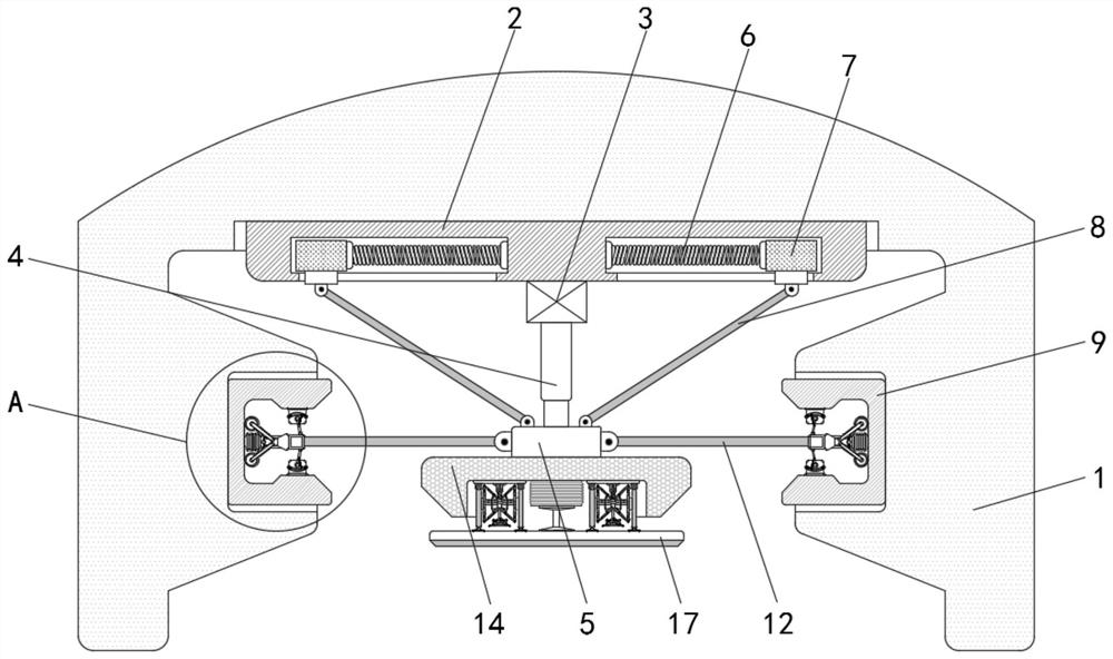
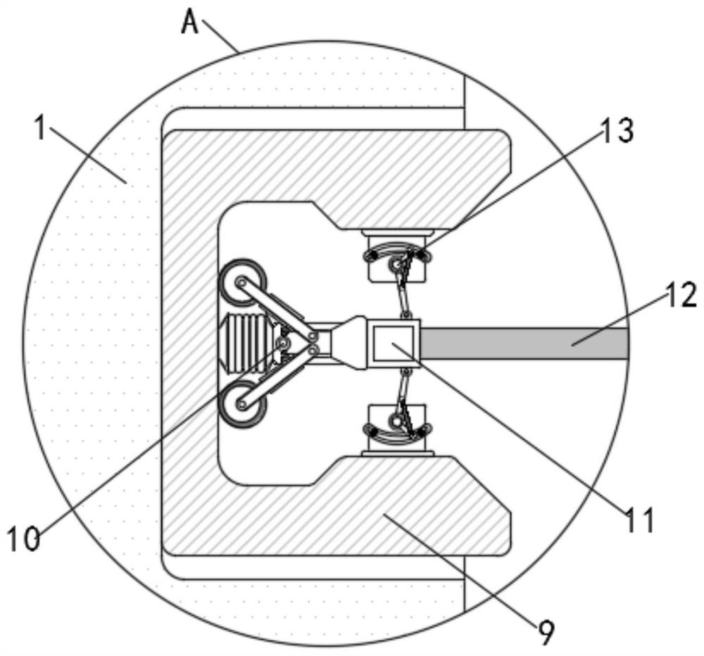
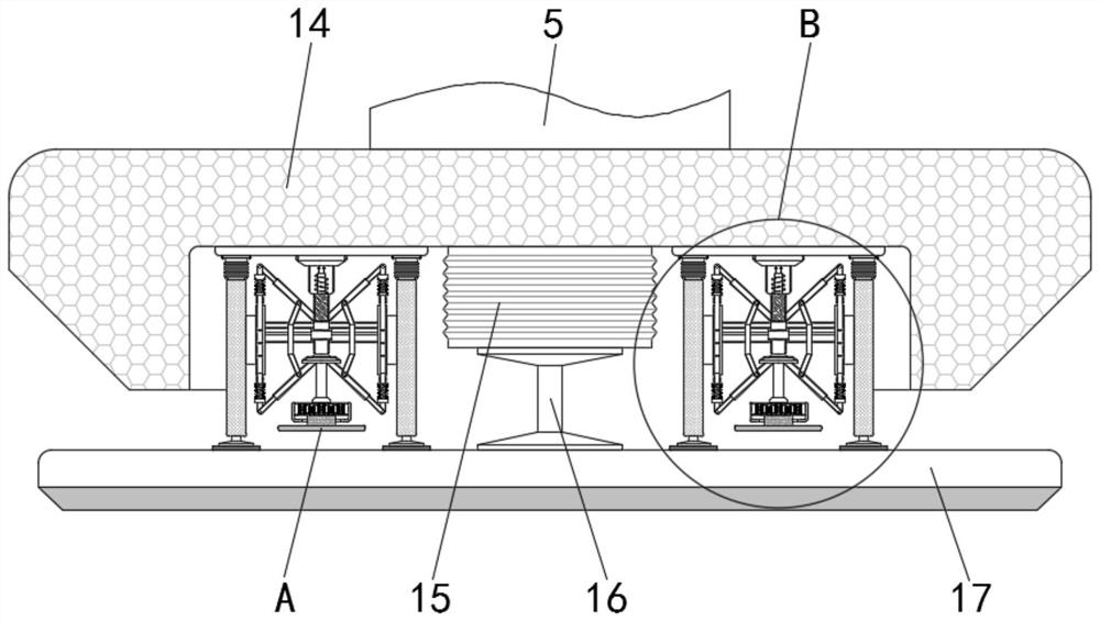
[0025] The present invention provides a tool correction auxiliary device for automatic hardware cutting equipment, which includes a main body 1, a fixed base 2 is fixedly installed on the top of the inner wall of the main body 1, and a driving device 3 is installed on the lower side of the fixed base 2. The lower side is provided with a driving telescopic rod 4, the lower end of the driving telescopic rod 4 is fixedly equipped with a movable part 5, and the inside of the fixed base 2 is provided with a movable groove, and the inner wall of the movable groove is provided with a spring mechanism 6, and the spring mechanism 6 The shaft end of the shaft is fixedly connected with a movable block 7, the lower side of the movable block 7 is movably equipped with a movable push rod 8, the lower end of the movable push rod 8...


PUM


Abstract

The invention provides a cutter deviation rectifying auxiliary device of automatic hardware cutting-off equipment. The cutter deviation rectifying auxiliary device comprises a main body, a fixed base is fixedly installed on the top of the inner wall of the main body, a driving device is installed on the lower side of the fixed base, a driving telescopic rod is installed on the lower side of the driving device, a movable part is fixedly mounted at the lower end of the driving telescopic rod, a movable groove is formed in the fixed base, a spring mechanism is mounted on the inner wall of the movable groove, and a movable block is fixedly connected to the shaft end of the spring mechanism. According to the cutter deviation correction auxiliary device of the automatic hardware cutting-off equipment, due to uncontrollable factors, a cutting-off cutter inclines, the lower end of a push rod is adjusted to drive an adjusting mechanism to achieve deviation correction of the cutting-off cutter, then the cutting-off cutter is reset, and therefore the purpose of effectively eliminating deviation of the cutting-off cutter is achieved; and meanwhile, the hardware cutting-off efficiency of the equipment and the production efficiency of manufacturers are improved, and the equipment is simple in structure, safe and reliable.

Description

technical field [0001] The invention belongs to the technical field of automatic machinery, and in particular relates to a tool deviation correction auxiliary device of automatic hardware cutting equipment. Background technique [0002] Hardware is an auxiliary and accessory finished product used in daily life and industrial production. In the early days, it was mostly made of metal materials such as gold, silver, copper, iron, tin, etc., hence the name. Now in addition to using various metal materials, it is also widely used. Made of plastic, glass fiber and other non-metallic materials, hardware has played an important role in the process of human survival and development. [0003] Nowadays, with the development of social economy and the refinement of social division of labor, hardware parts are gradually enriched and perfected, and there are more and more varieties. Due to the needs of products, hardware parts are often truncated during the production process. Now In the...

Claims


Application Information

Patent Timeline
IPC IPC(8): B23Q15/24
CPCB23Q15/24
Inventor 程刚
Owner 珠海可立自动化技术有限公司
Learn More