
Conveying device of atrial shunt

The technology of a conveying device and a shunt, which is applied in the field of medical devices, can solve the problems of complicated conveying device, etc., and achieve the effects of simplifying the preparation process, low cost, and increasing sealing.

Inactive Publication Date: 2021-08-10
QICHEN (SHANGHAI) MEDICAL EQUIP CO LTD
View PDF3 Cites 3 Cited by
  • Summary
  • Abstract
  • Description
  • Claims
  • Application Information

AI Technical Summary

Problems solved by technology

However, currently on the market, the delivery devices specially used for atrial shunts are too complicated, causing a large economic burden to patients and their families. Therefore, it is necessary to develop a simple, economical and practical implantable atrial shunt device to reduce costs. Benefiting patients and their families

Method used


Image

  • Conveying device of atrial shunt
  • Conveying device of atrial shunt
  • Conveying device of atrial shunt

Examples


Embodiment 1

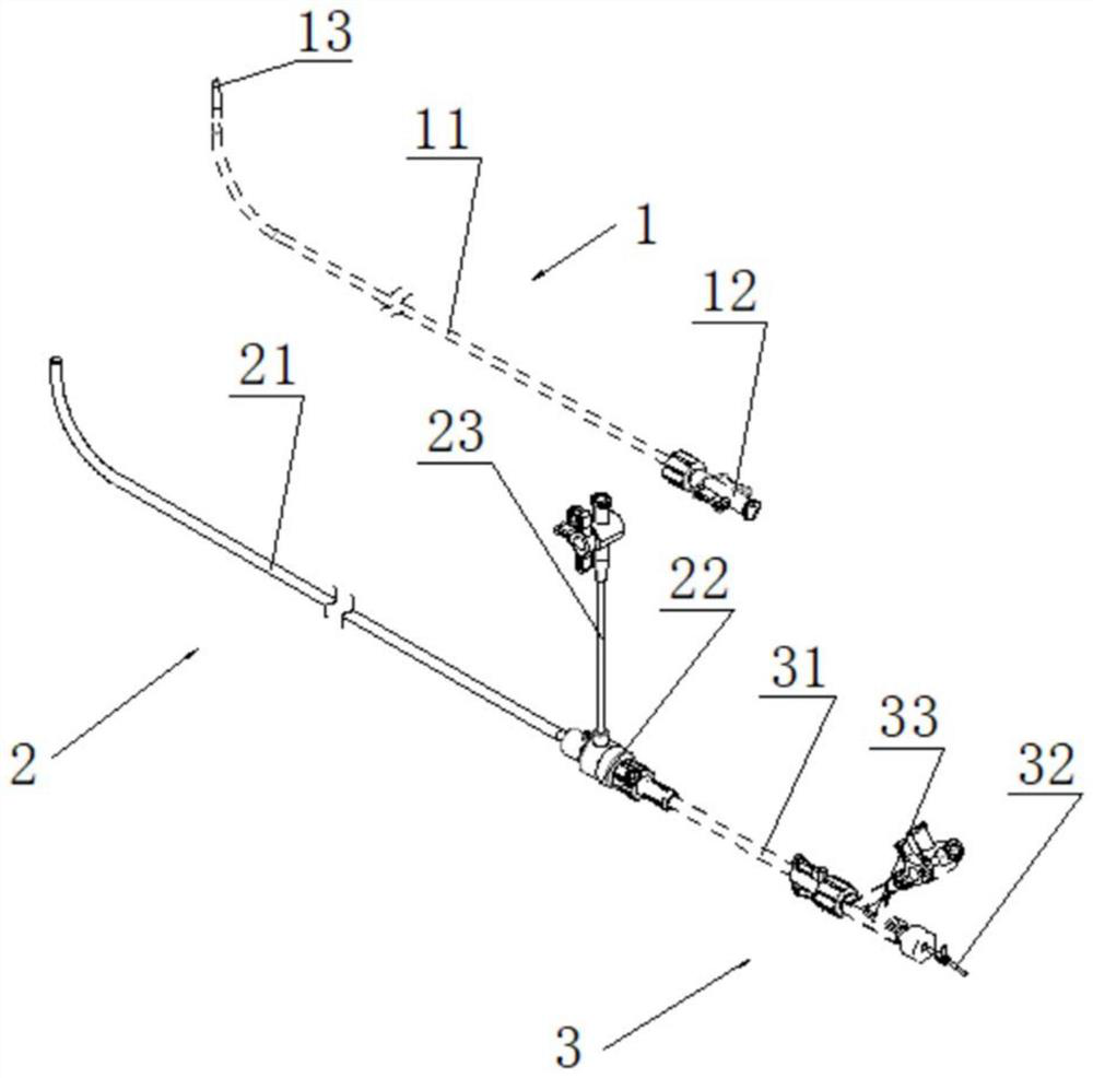
[0041] Such as Figure 1-9 As shown, the delivery device of the atrial shunt in this embodiment is used to deliver the atrial shunt 5 to the interatrial septum 4, and then through the atrial shunt 5 to redistribute the interatrial pressure and reduce the interatrial pressure of the left and right atria.

[0042]Specifically, the delivery device for an atrial shunt includes a delivery structure 2, an expansion structure 1, and a loading structure 3. The delivery structure 2 includes a delivery sheath 21 and a delivery handle 22. The expansion structure 1 includes a dilation catheter 11 and a reamer handle 12. The loading structure 3 includes a shunt loading part 31 and a pushing part 32;

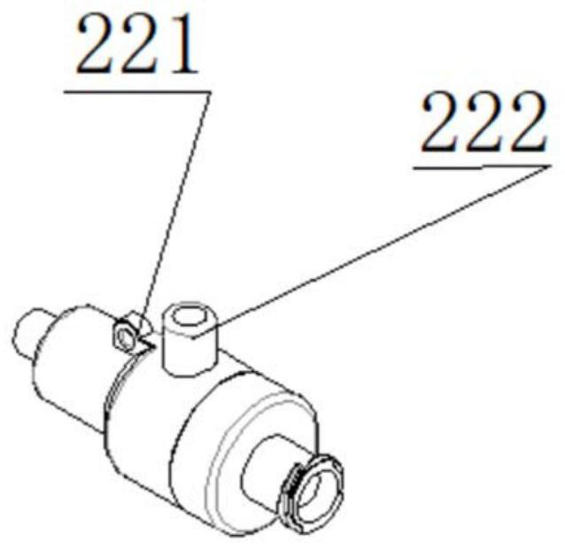
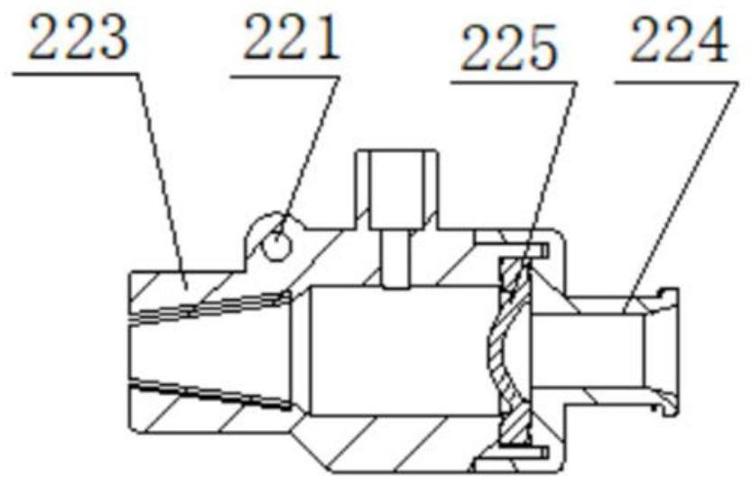
[0043] In the conveying structure 2, the conveying handle 22 is a hollow stepped cylindrical structure. Along the radial direction, the inner diameters at both ends are smaller, and the inner diameter in the middle is larger. There is an emptying port 222 in the middle, and the emptying port ...

Embodiment 2

[0058] The difference between the delivery device of the atrial shunt of this embodiment and the first embodiment is that:

[0059] Such as Figure 10-11As shown, the connection mode between the delivery handle 22 and the delivery sheath tube 21 is changed from a fixed connection to a threaded compression fit between the sheath tube connection part 223 and the delivery sheath tube 21 through a delivery handle nut 226, and the delivery handle nut 226 is connected to the sheath tube The distal end of the connecting part 223 is screwed, and the contact part has a slope. The outer periphery of the delivery handle nut 226 is provided with a nut bar-shaped boss 2261. Specifically, the outer periphery of the far end of the delivery handle 22 is provided with a connecting thread, and the outer periphery of the sheath tube connecting part 223 It is a circular platform whose diameter gradually increases from the distal end to the proximal end, and the inner circumference is a circular p...


PUM

PropertyMeasurementUnit
Angleaaaaaaaaaa

Abstract

The invention relates to the technical field of medical instruments, in particular to a conveying device of an atrial shunt. The device comprises a conveying structure, an expansion structure and a loading structure, the conveying structure comprises a conveying sheathing canal and a conveying handle, the expansion structure comprises an expansion catheter and a reaming piece handle, the loading structure comprises a shunt loading part and a pushing part, a first circular truncated cone is arranged at the far end of the conveying sheathing canal, the lower portion of the proximal end of the first circular truncated cone is provided with a first curved part, the far end of the dilation catheter is provided with a second circular truncated cone, and the lower portion of the proximal end of the second circular truncated cone is provided with a second curved part. The conveying device of the atrial shunt is simple in structure and low in cost, popularization and application of the conveying device in the field of medical instruments are facilitated, meanwhile, conveying of the conveying device is smoother, the sealing performance of the system is high, the preparation process is simplified, and the process cost is greatly reduced.

Description

technical field [0001] The invention relates to the technical field of medical devices, in particular to a delivery device for an atrial shunt. Background technique [0002] Heart failure, referred to as heart failure, refers to the failure of the venous blood to fully discharge the heart due to cardiac systolic and / or diastolic dysfunction, resulting in blood stasis in the venous system and insufficient blood perfusion in the arterial system, resulting in cardiac circulation syndrome. , This kind of disorder symptom group manifests as pulmonary congestion and vena cava congestion. [0003] According to the location of heart failure, it can be divided into: (1) left heart failure: refers to heart failure caused by left ventricular compensatory dysfunction, which is relatively common in clinical practice, and is characterized by pulmonary circulation congestion; (2) right heart failure: simple heart failure Right heart failure is mainly seen in cor pulmonale and some congeni...

Claims


Application Information

Patent Timeline
IPC IPC(8): A61B17/00A61B17/34A61B17/12
CPCA61B17/00A61B17/34A61B17/12A61B2017/12004
Inventor 梁玉晨
Owner QICHEN (SHANGHAI) MEDICAL EQUIP CO LTD
Learn More