An optical imaging system

An optical imaging system and imaging component technology, applied in the field of optical detection, can solve problems such as low efficiency, and achieve the effects of reducing burden, improving mobility, and reducing center of gravity

Active Publication Date: 2022-04-22
深圳市华拓半导体技术有限公司
View PDF10 Cites 0 Cited by
  • Summary
  • Abstract
  • Description
  • Claims
  • Application Information

AI Technical Summary

Problems solved by technology

[0004] In view of the above-mentioned related technologies, the applicant believes that the current appearance inspection of the object under test has the defect of low efficiency

Method used


Image

  • An optical imaging system
  • An optical imaging system
  • An optical imaging system

Examples


Embodiment Construction

[0033] The application will be described in further detail below in conjunction with the accompanying drawings.

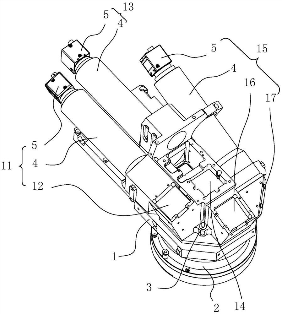
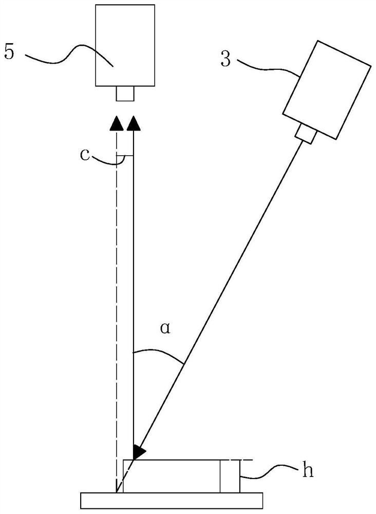
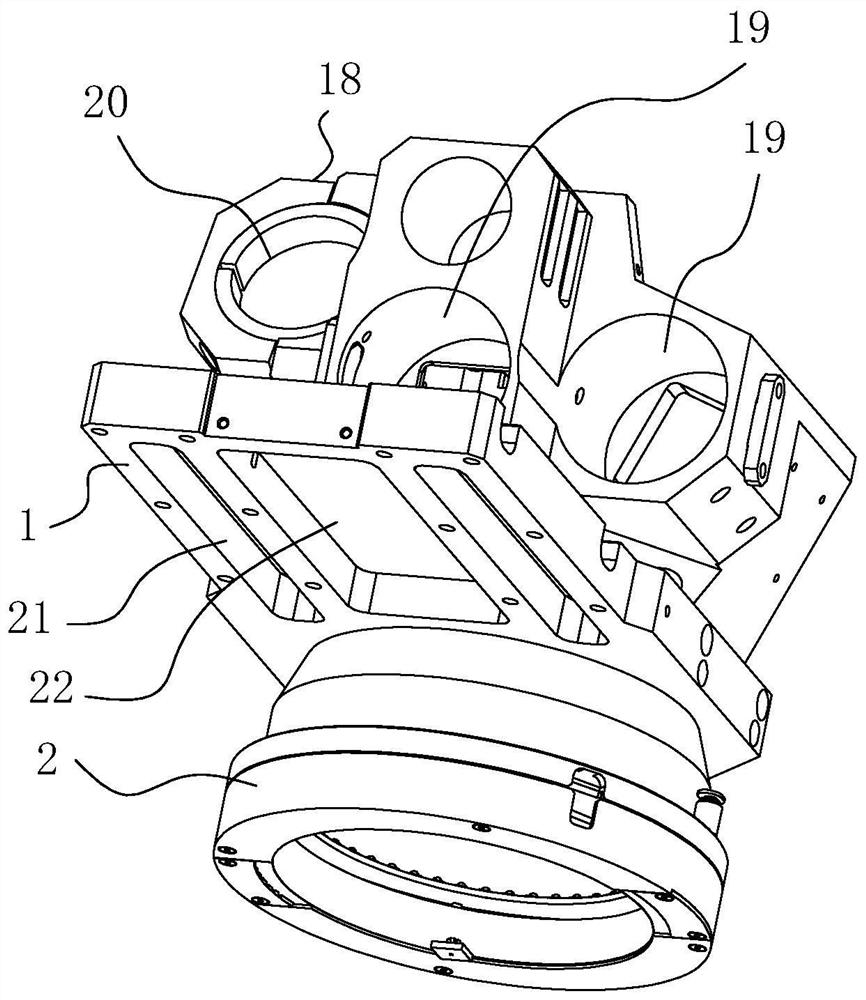
[0034] refer to figure 1 , an optical imaging system, comprising a bracket 1, the bracket 1 is provided with a lower cover body 2 and a photographing device, the photographing device includes a light source device, a laser emitter 3 and a plurality of imaging components, and the light source device is installed in the lower cover body 2; each An imaging assembly includes lens barrel 4, a camera 5 for being installed on the light-emitting end of lens barrel 4, and a reflector group for reflecting light into the light-incoming end of lens barrel 4; a plurality of reflector groups are installed at different angles respectively Support 1, the light-incident end of each reflector group is all communicated with the inner wall of lower cover body 2, and one of them reflector group is positioned at the upper end of lower cover body 2; The straight line where the laser emi...


PUM


Abstract

The present application relates to the technical field of optical detection, in particular to an optical imaging system, including a bracket, the bracket is provided with a lower cover and a photographing device, and the photographing device includes a light source device, a laser emitter and a plurality of imaging components; each imaging component Both include a lens barrel, a camera and a reflector group; multiple reflector groups are installed on the bracket at different angles; the normal of the plane where the light incident end of one of the reflector groups is located is in a certain line with the laser emission route of the laser transmitter. angle. Beneficial effects of the present application 1. By arranging a plurality of imaging components, the object under test is photographed and imaged at multiple angles of view synchronously, so that the detection efficiency is improved and the speed of appearance inspection for a large number of objects under test is accelerated. 2. By setting the laser transmitter, the imaging component can achieve automatic focus when shooting each object under test, improve the clarity of the image, and reduce the loss of details in the image.

Description

technical field [0001] The present application relates to the technical field of optical detection, in particular to an optical imaging system. Background technique [0002] Semiconductor chips refer to electronic components whose conductivity is between conductors and insulators at room temperature. In the manufacturing process of semiconductor chips, it is necessary to use the semiconductor chip as the object to be tested for appearance inspection. One of the detection methods is to capture and image the semiconductor chip through the camera, and process and analyze the characteristics of the measured object in the generated image to obtain the details of the measured object. [0003] In order to obtain as many details of the measured object as possible, it is necessary to shoot the measured object from multiple angles of view. The conventional method is to shoot the measured object from multiple angles one by one. The number increases exponentially, and when the convent...

Claims


Application Information

Patent Timeline
Patent Type & Authority Patents(China)
IPC IPC(8): G03B15/02G03B15/03G03B15/06G01N21/84G01N21/01H01L21/66
CPCG03B15/02G03B15/03G03B15/06G01N21/84G01N21/01H01L22/12G01N2201/061G01N2201/06G01N2201/06113
Inventor 罗建华
Owner 深圳市华拓半导体技术有限公司
Why Eureka
Try Eureka