
Rapid drying method for building prefabricated part manufacturing concrete

A technology for rapid drying and prefabrication, which is used in drying, drying machines, drying solid materials and other directions to achieve the effects of improving drying quality, improving use efficiency and accelerating drying.

Pending Publication Date: 2021-08-06
湖北汇宜建设工程有限公司
View PDF0 Cites 0 Cited by
  • Summary
  • Abstract
  • Description
  • Claims
  • Application Information

AI Technical Summary

Problems solved by technology

[0004] Aiming at the deficiencies in the use process of the existing concrete rapid drying equipment proposed in the background technology, the present invention provides a concrete rapid drying equipment and drying method for manufacturing building prefabricated parts, which has the ability to use the gas to be discharged to dry the prefabricated parts Rotate to dry evenly, improve the drying quality and efficiency of prefabricated parts and the advantages of resource utilization efficiency, and solve the technical problems raised in the above-mentioned background technology

Method used


Image

  • Rapid drying method for building prefabricated part manufacturing concrete
  • Rapid drying method for building prefabricated part manufacturing concrete
  • Rapid drying method for building prefabricated part manufacturing concrete

Examples


Embodiment Construction

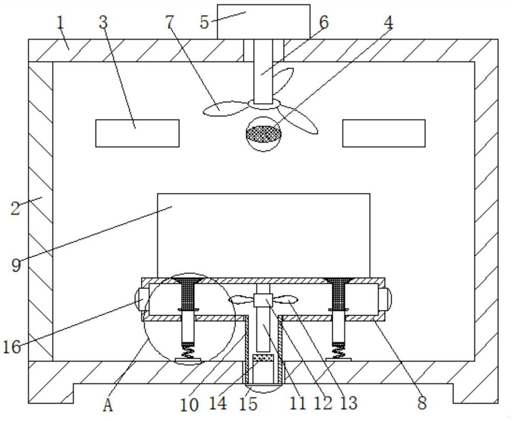
[0028] The following will clearly and completely describe the technical solutions in the embodiments of the present invention with reference to the accompanying drawings in the embodiments of the present invention. Obviously, the described embodiments are only some, not all, embodiments of the present invention. Based on the embodiments of the present invention, all other embodiments obtained by persons of ordinary skill in the art without making creative efforts belong to the protection scope of the present invention.

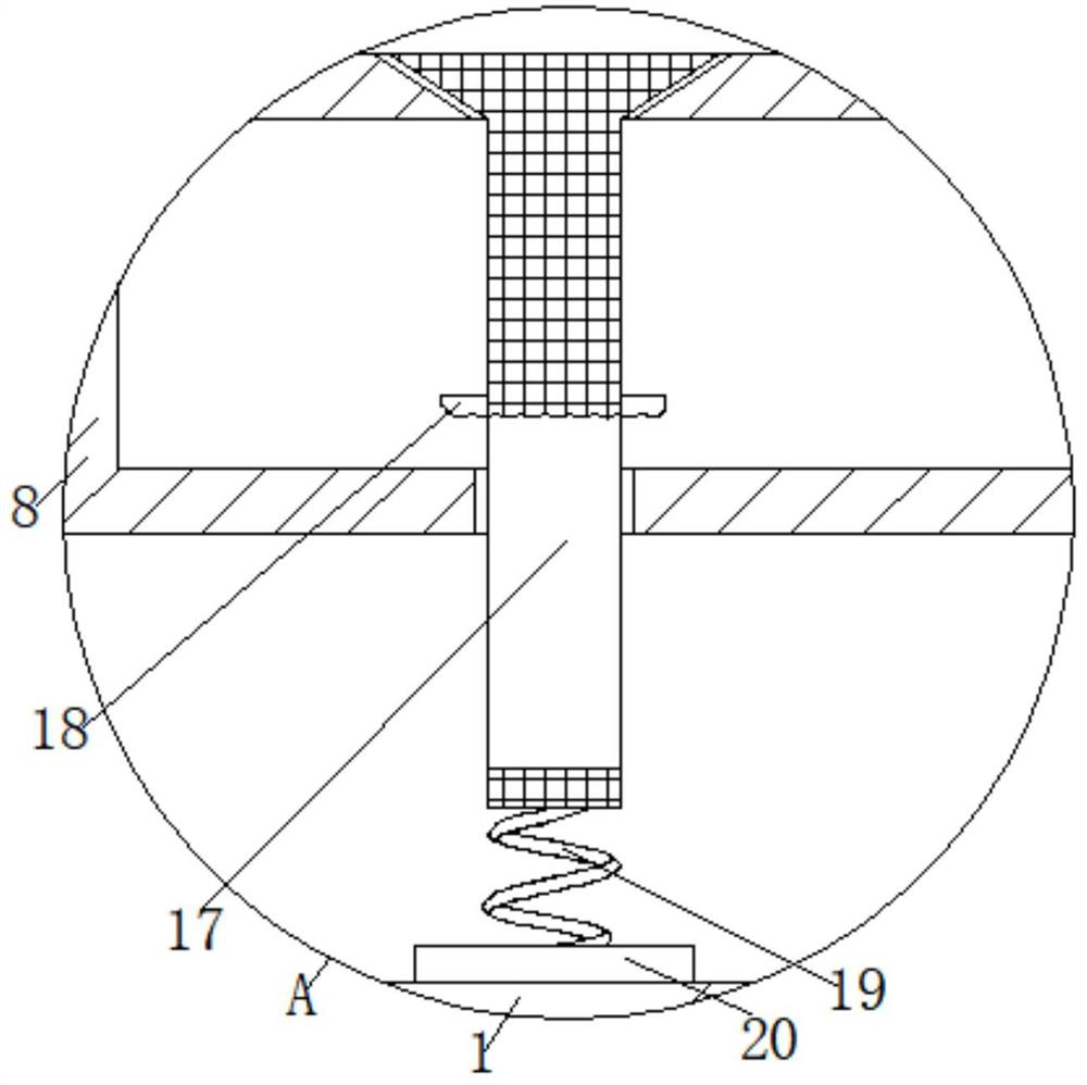
[0029] see Figure 1-5 , a rapid drying equipment for manufacturing prefabricated concrete, including a body 1, one side of the body 1 is movably connected to an organic door 2, and a heater 3 is fixedly connected to the inside of the body 1, and is located inside the body 1 at the same level as the door 2 A gas inlet 4 is fixedly connected, and a motor 5 is fixedly connected to the top of the body 1 corresponding to the gas inlet 4. A hole is opened on the to...


PUM


Abstract

The invention relates to the technical field of prefabricated concrete production and manufacturing, and discloses a rapid drying method for building prefabricated part manufacturing concrete. A machine body is included, one side of the machine body is movably connected with a machine door, a heater is fixedly connected to the upper side of the interior of the machine body, a gas inlet is fixedly connected in the position, located on the same horizontal plane with the machine door, in the machine body, a motor is fixedly connected in the position, corresponding to the gas inlet, of the top end of the machine body, a hole is formed in the top end of the machine body, the bottom end of the motor is movably connected with one end of a rotating shaft in a sleeving mode through the hole, the other end of the rotating shaft is fixedly connected with a machine fan in a sleeving mode, a hole is formed in the middle of the bottom end in the machine body, and the machine body is fixedly connected with one end of an exhaust channel through the hole. According to the method, power is provided for blades through gas needing to be exhausted, the blades rotate to drive a disc frame to rotate, heated airflow can evenly dry a prefabricated part from different angles, the drying quality of the prefabricated part is improved, and meanwhile, the drying efficiency of the prefabricated part is also improved.

Description

technical field [0001] The invention relates to the technical field of prefabricated concrete production and manufacturing, in particular to a rapid drying method for manufacturing prefabricated concrete. Background technique [0002] Prefabricated parts refer to concrete products that are poured in advance elsewhere and then welded and installed at the designated location on the construction site. Prefabricated concrete parts are widely used in construction, transportation, water conservancy and other fields, and play an important role in the national economy. , Such as prefabricated concrete column foundation, external window panels, etc. are all prefabricated concrete parts. The main production steps of concrete prefabricated parts are: mixing, forming, drying and demoulding, among which the drying step is conducive to the improvement of the quality and production efficiency of concrete prefabricated parts. [0003] However, there are still some defects in the working pr...

Claims


Application Information

Patent Timeline
Patent Type & Authority Applications(China)
IPC IPC(8): F26B11/18F26B21/00F26B25/00F26B25/12F26B25/18
CPCF26B11/18F26B21/001F26B25/002F26B25/12F26B25/18
Inventor 望春来陈定平
Owner 湖北汇宜建设工程有限公司
Learn More