


Quick Research
Generate reliable direction feasibility study reports for your R&D in just a few steps.

Technical Q&A
Discover and master advanced knowledge NOW. Basics, ideas, possibilities, all at once.

Find Solutions
As an expert in R&D theories, this can generate solutions to your technical problems instantly.

Evaluate Feasibility
Analyze your overall solution with one click, know your potential R&D risks in advance.

Monitor Landscape
Get weekly tech updates, stay abreast of the latest tech innovations and key insights.
A water purification system and purification method
A water purification and water body technology, applied in the field of water treatment, can solve the problems of easy loss of catalytic materials, difficult separation, and low mass transfer efficiency, and achieve the effects of low sewage treatment efficiency, reduced scale formation, and improved mass transfer rate
- Summary
- Abstract
- Description
- Claims
- Application Information
AI Technical Summary
Problems solved by technology
Method used
Image


Examples
preparation example Construction
[0173] |1. Preparation of substrate materials|
[0174] A transition metal aluminum foil with a thickness of 200 μm was selected as the basic material for the preparation of the base material; the specific steps are as follows:
[0175] 1) drawing: such as Figure 12 As shown in a, the aluminum foil (upper and lower surfaces) is subjected to high-temperature annealing, degreasing, grinding, and pre-polishing treatment, followed by wire drawing treatment, so that the upper and lower surfaces of the transition metal aluminum foil form several substantially parallel strips with a width of about 50 ± 10nm, Stripes with a depth of 3±1nm and a spacing of 50±10nm are washed with ethanol and deionized water respectively, and dried in an oven at 50°C for later use. The obtained wire-drawn material has the following properties: Figure 12 the surface shown in b;
[0176] 2) Anodizing: use the titanium plate as the cathode, use the pretreated aluminum foil as the anode, use 50g / L oxali...
Embodiment 1
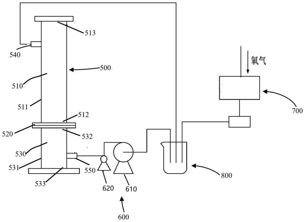
[0199] Such as figure 1 As shown, the water purification system in this example includes a first device 500 , a second device 600 and a gas generating device 700 . Wherein, the second device 600 includes a water inlet regulating device 610 (regulating pump) and an internal circulation regulating device 620 (regulating pump); the first connection structure 520 in the first device 500 is a gasket with holes, and The central area has several, uniformly distributed small holes that can pass through the water body / gas, which is the central area 521 with holes; the gas generating device 700 is an ozone generating device 710, and the gas generating device 700 is directly connected to the water body to be treated The collection device 800 is connected, and the gas is directly charged into the collection device 800 for water to be treated. And the effluent water from the first device 500 flows back to the untreated water collection device 800 through the outlet 540 for circular purif...
Embodiment 2
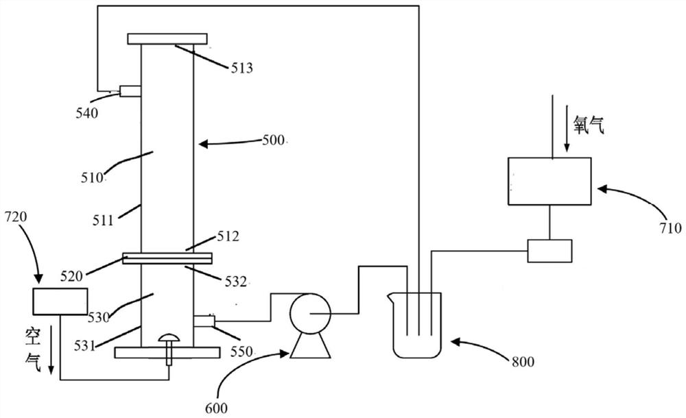
[0214] Such as figure 2 As shown, the water purification system in this example includes a first device 500 , a second device 600 and a gas generating device 700 . Wherein, the second device 600 is a water inlet regulating device 610 (regulating pump); the first connecting structure 520 in the first device 500 is a gasket with holes, and the central area has several uniformly distributed The small hole for water / gas to pass through is the central area 521 with holes; the gas generating device 700 is an ozone generating device 710 , and the gas generating device 700 is directly connected to the second area 530 of the first device 500 . And the effluent water from the first device 500 flows back to the untreated water collection device 800 through the outlet 540 for circular purification treatment.
[0215] In this embodiment, the filling volume of the light insoluble solid catalyst 514 accounts for 50% of the internal volume of the first region 510 .
[0216] In addition, th...
PUM
| Property | Measurement | Unit |
|---|---|---|
| density | aaaaa | aaaaa |
| density | aaaaa | aaaaa |
| thickness | aaaaa | aaaaa |
Abstract
Description
Claims
Application Information
 - R&D Engineer
- R&D Manager
- IP Professional
- Industry Leading Data Capabilities
- Powerful AI technology
- Patent DNA Extraction
Browse by: Latest US Patents, China's latest patents, Technical Efficacy Thesaurus, Application Domain, Technology Topic, Popular Technical Reports.
© 2024 PatSnap. All rights reserved.Legal|Privacy policy|Modern Slavery Act Transparency Statement|Sitemap|About US| Contact US: help@patsnap.com