
An enameled wire painting equipment

A paint spraying equipment and enameled wire technology, which is applied in spray booths, spraying devices, liquid spraying devices, etc., can solve the problems of non-combination, reducing the yield of enameled wire spraying equipment, consumption of power resources, etc., and achieve the effect of saving waste

Active Publication Date: 2022-04-22
华尔达线缆集团有限公司
View PDF22 Cites 0 Cited by
  • Summary
  • Abstract
  • Description
  • Claims
  • Application Information

AI Technical Summary

Problems solved by technology

[0003] However, the existing enameled wire painting equipment has the following problems in application: the external working environment of the enameled wire painting equipment is complex, when the operator moves objects or freely moving foreign objects, and accidentally picks up the external enameled wire, the enameled wire painting equipment is stopped immediately. This method needs to divide the equipment to cut the severely bent part. Manual cutting requires the operator to use a lot of force. The use of power division equipment will increase the cost of enameled wire painting equipment, and consume power resources at the same time. It does not meet the concept of green and environmental protection development , Secondly, there is insulating varnish inside the paint storage equipment. When the connected high-pressure air pump fills the interior with gas, part of the insulating varnish will flow back into the interior of the paint pipe, resulting in the inability of this part of the insulating varnish to be sprayed out through the spray head. Finally, the copper The external part of the wire is easy to contact with debris in the air. If it is not cleaned, it will be fixed by insulating varnish spraying. This operation will reduce the yield of enameled wire painting equipment

Method used


Image

  • An enameled wire painting equipment
  • An enameled wire painting equipment
  • An enameled wire painting equipment

Examples


Embodiment Construction

[0036] In order to further illustrate the various embodiments, the present invention provides accompanying drawings, which are part of the disclosure of the present invention, and are mainly used to illustrate the embodiments, and can be used in conjunction with the relevant descriptions in the specification to explain the operating principles of the embodiments, for reference Those of ordinary skill in the art should be able to understand other possible implementations and advantages of the present invention. The components in the figures are not drawn to scale, and similar component symbols are generally used to represent similar components.

[0037] According to an embodiment of the present invention, an enameled wire painting equipment is provided.

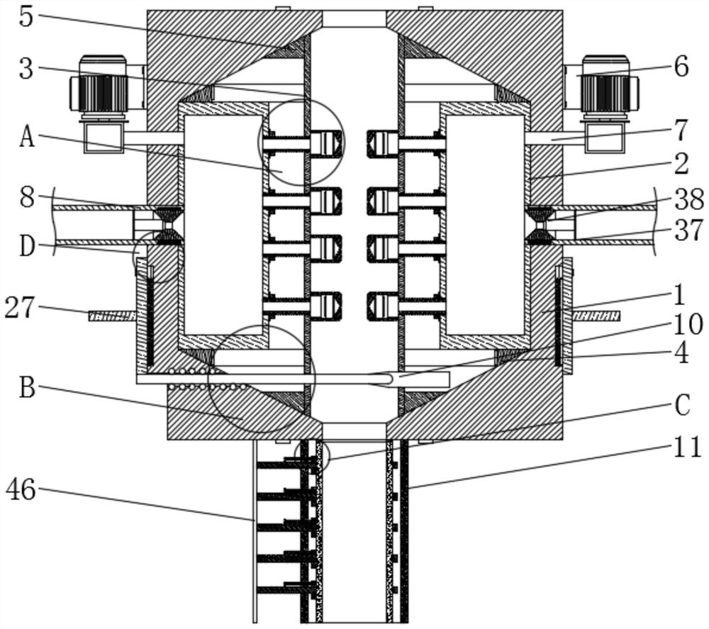
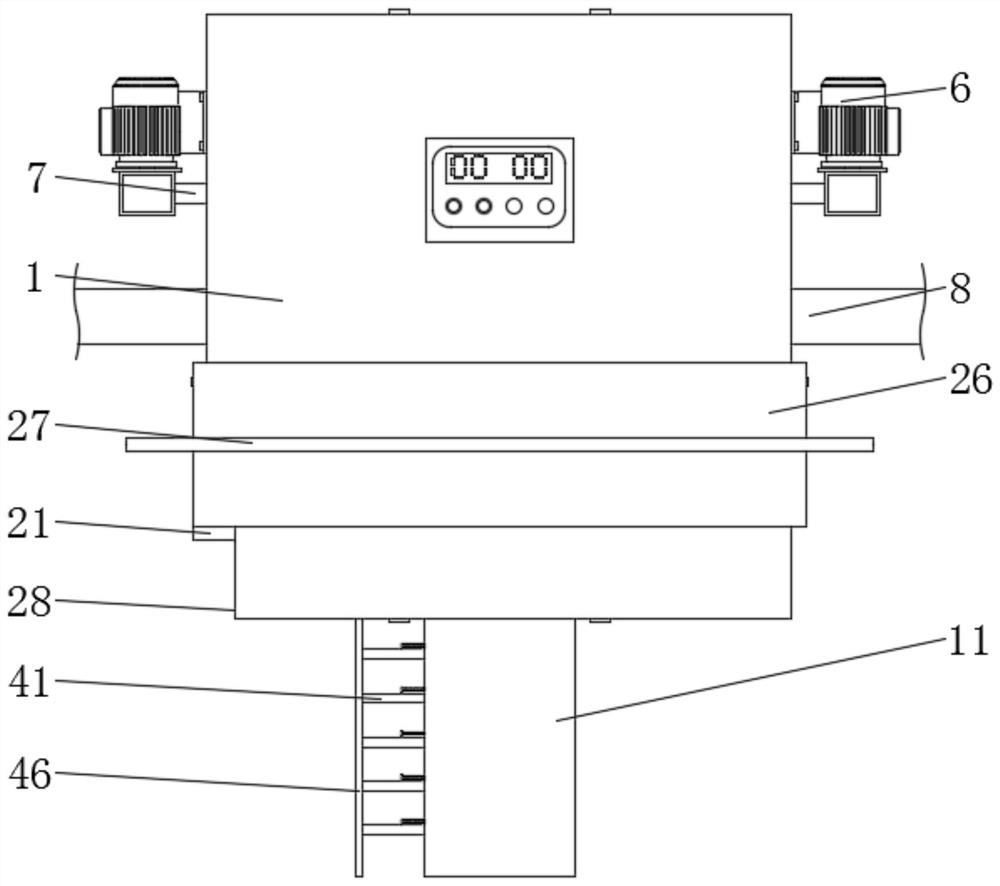
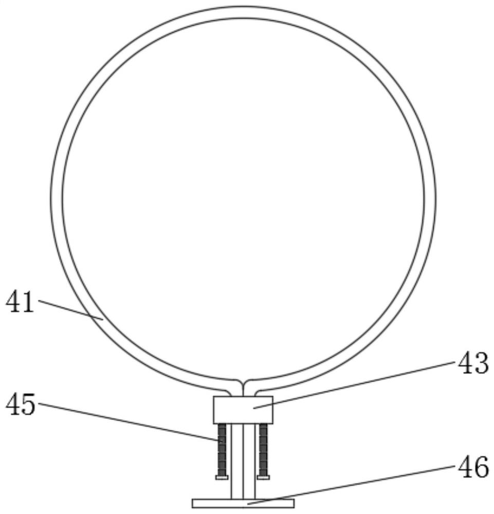
[0038] Now in conjunction with accompanying drawing and specific embodiment the present invention is further described, as Figure 1-9 As shown, an enameled wire painting equipment according to an embodiment of the present inv...


PUM


Abstract

The invention discloses an enameled wire painting equipment, which comprises a casing, a paint storage box and an isolation tube are fixedly installed inside the casing, and tapered mounting rings are fixedly installed at both ends of the paint storage box. Both ends of the isolation tube are sleeved with tapered mounting blocks, and the outer side walls of the casing are equipped with two sets of high-pressure air pumps and paint inlet pipes, and one end of the two sets of high-pressure air pumps is snap-fitted with an air guide tube One end of the two groups of air guide pipes and the two groups of paint inlet pipes runs through the outer side wall of the shell and the paint storage box, the interior of the two groups of paint inlet pipes is slidingly installed with anti-backflow plugs, and the isolation pipes A dividing blade is slidingly installed on the side wall, and a cleaning pipe is fixedly installed on the lower part of the shell. Beneficial effects: the invention uses the splitting blade, and through the set splitting blade, the operator can use his own gravity to cut the enameled wire without adding power equipment, which saves the waste of power resources and conforms to the concept of green and environmental protection development.

Description

technical field [0001] The invention relates to the field of enameled wire painting, in particular to an enameled wire painting equipment. Background technique [0002] Enameled wire refers to a metal wire that uses insulating varnish as an insulating coating and is used to wind electromagnetic coils. It is also called electromagnetic wire. Enameled wire is a main variety of winding wire. , and then painted and baked for many times, it has four major properties: mechanical properties, chemical properties, electrical properties, and thermal properties. When actually producing enameled wires, enameled wire spraying equipment is often used to complete the enameled wires. It has the advantages of simplicity, uniform painting, stability and high efficiency. [0003] However, the existing enameled wire painting equipment has the following problems in application: the external working environment of the enameled wire painting equipment is complex, when the operator moves objects o...

Claims


Application Information

Patent Timeline
Patent Type & Authority Patents(China)
IPC IPC(8): B05B9/04B05B16/20B05B15/00B21F11/00B21F23/00B08B1/02B08B1/20
CPCB05B9/0409B05B9/0423B05B16/20B05B15/00B21F11/00B21F23/00B08B1/20B08B1/143
Inventor 吴文红
Owner 华尔达线缆集团有限公司
Learn More