[0016] It is therefore the direction of this invention a
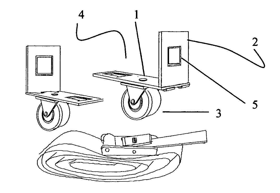
Carriage Platform
Assembly, FIG. 1, 1B, that incorporates a
carriage platform, FIG. 3, in combination with
strapping material that secure wheel or wheel like structures, FIG. 4, to a designated article, FIG. 23, 23B,23C providing a flexible and custom mobility without adding significant weight or dimension to the article needing mobility.
[0019] The present invention can provide mobility using
weight transfer.
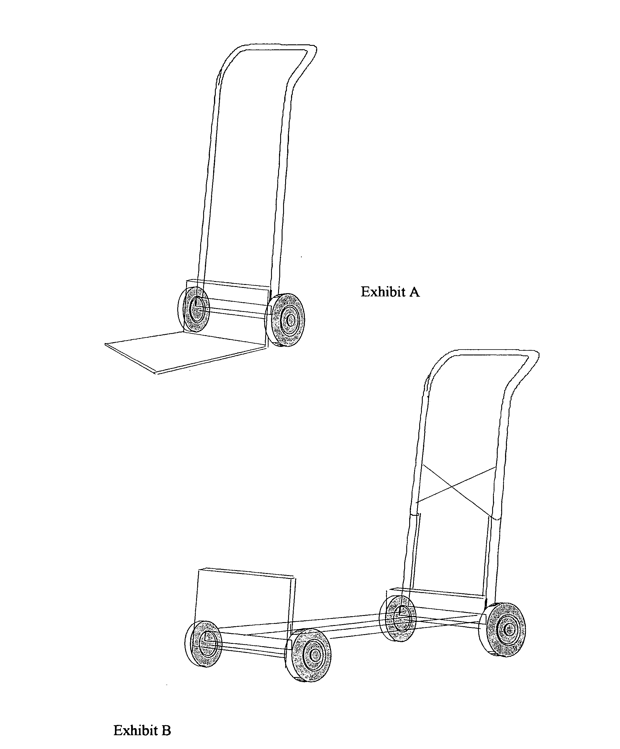
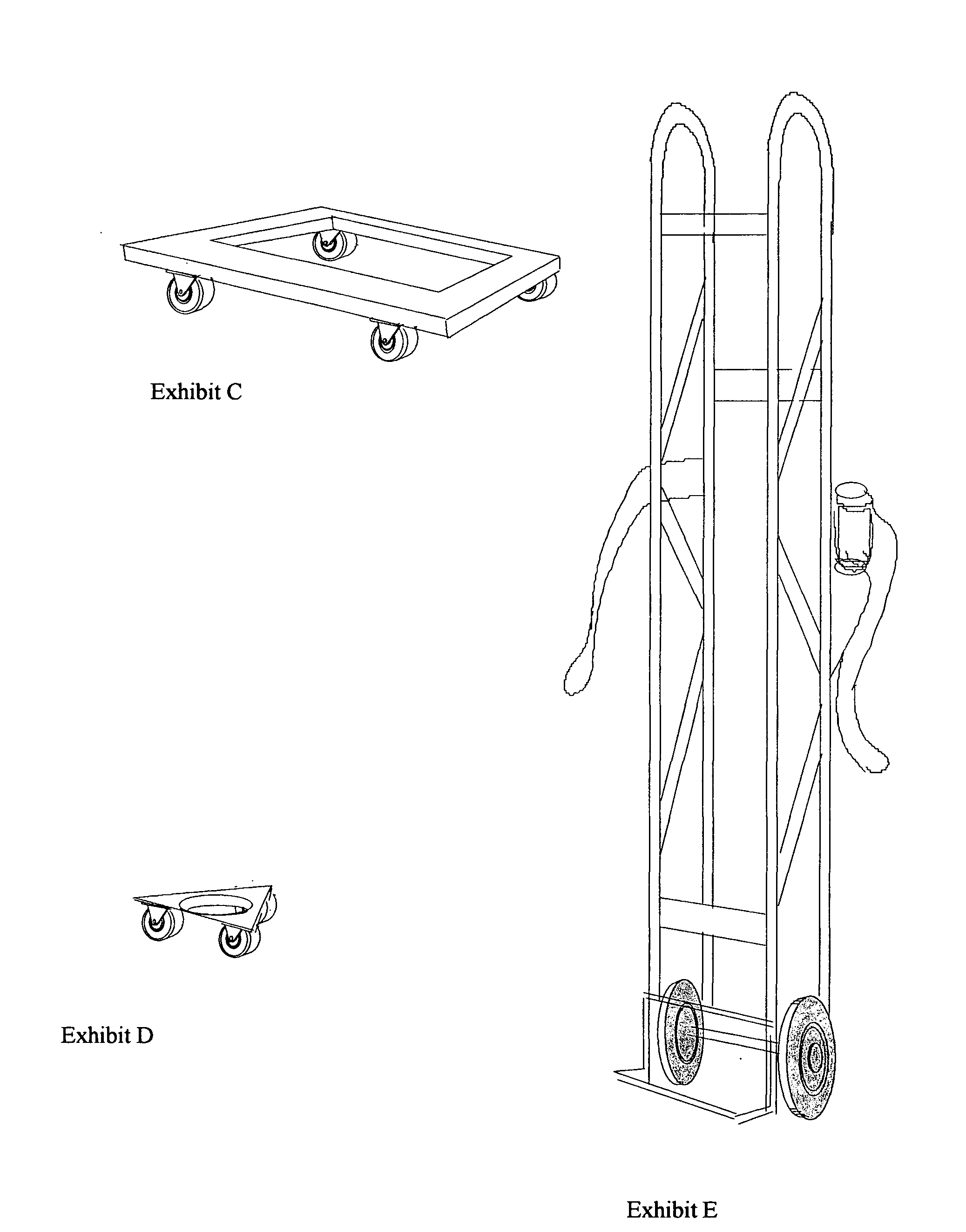
Weight Transfer is required with the use of a traditional Hand
Truck and Appliance Hand Truck, Exhibit A, E, putting a portion of the article weight on the single person operating the Hand Truck. In the present invention an article that derives its mobility from the a single
carriage platform
assembly, FIG. 29, or a double
carriage platform, FIG. 6,21, will exercise the properties of
weight transfer to aid in its mobility,
weight transfer is accomplished by lifting one end of the article and allowing the end supporting the wheels to move along the surface. With the present invention
Weight transfer can be reduced or eliminated when applying an additional
Carriage Platform assembly, FIG. 2,22, 23D 25,26, 27,28, 29B, distributing the article weight over additional carriage platforms. Distributing the article weight will provide for single or multiple operator force and direction to support mobility. Operation is a simple pushing or pulling motion of the article along the intended surface, without the requiring the operator to carry a portion of the transferred weight. Directional changes are also facilitated by a simple push or pull motion by one or more operators assisted by the
multi directional swivel wheels attached to the carriage platform. Because there is no framed structure that is responsible for moving an article with the present invention allowing several operators to apply force or direction to all edges of the article needing mobility.
[0022] The present invention accomplishes this improved movement without adding a frame dimension to the article requiring mobility, due to the
strapping or banding device being used to hold the carriage platform and its wheel or wheel like structure around the article perimeter. This application of strapping or banding device holding the carriage platform also allows for mobility security of the article. With the carriage platform and its wheel or wheel like structures firmly secured around the article, there is less opportunity for the article to slip off during movement or be left behind when an article is lifted up
stairs or over a curbs or barriers, FIG. 24,24B,24C. The same
system of strapping or banding device can be applied in unlimited configurations, FIG. 8B,8C, forward, back, crisscross, around the top, around the bottom, up the sides and around articles with varying shapes and textures or around articles with little or no definitive shape, such as a tarp full of leaves and twigs, FIG. 27, or multiple articles with many surface planes and angles, FIG. 28, as well as a single plane with multiple pieces, FIG. 26. The strapping portion of the invention provides hand holding areas along the articles perimeter, to assist with mobility. Additionally, strapping material can form auxiliary handles to help with the push, pull motion used to create mobility and provide direction. FIG. 7B. This strapping
system forms a flexible,
custom fitting mobility component that secures the carriage platform without marring or damaging the article it is holding. Several carriage platforms can be placed along a single length of strapping, providing mobility in several directions if needed, with an auxiliary carriage platform, FIG. 20C, attached to a select carriage platform, FIG. 20, movement up or down a stair case can be assisted with the auxiliary wheel riding along the stair raisers, reducing the need for article lifting or to prevent friction damage on an article pulled up or placed down a stair case.
[0023] Carriage platforms have an unlimited format array, FIG. 3,9,10,11,12,13,14,15,16,17,18, Illustrate just a few applications of carriage platforms with wheel and wheel like structures, but by no means suggest all the possible applications available within this invention. These carriage platforms do provide several grouping that can be considered. Carriage platforms can be affixed permanently with its wheel structure, FIG. 10,11,14, to the strapping component or removed with the proper tools. Carriage Platforms can also be separate and applied to strapping with no tools before strapping is applied to an article, or after strapping is already applied to an article, there are unlimited designs that allow the Carriage Platform with its wheel structure to be secured to strapping when mobility is required, or removed from the strapping when mobility is no longer needed, FIG. 1,3,4,9,12,13, 15,16, illustrate several formats of loops, snaps, and locks that will allow this simple removable Carriage Platform with its wheel structure, but by no means represents all the possible applications. The present invention also allows the Carriage Platform to be placed on the strapping component without its wheel structure, FIG. 17,18, and the wheel structure, FIG. 5, can be applied when mobility is required. This application can assist article storage and when mobility is required simply attach the wheel structures. This embodiment of a carriage platform can be produced inexpensively and disposed of when the strapping is removed from the article, allowing the wheel structures to be used again.
[0041] Minimal storage of the Carriage Platform assemblies allow them to be carried at all times with reduced storage to
performance ratio. Example four Carriage platforms with wheel and strapping assembly stored in a 6″×8″×4″ area could provide mobility assist to a
package 60″×60″×60″
