
Grinding machine tool for metal machining

A metal processing and grinding machine technology, used in metal processing equipment, grinding machine parts, grinding machines, etc., can solve the problems of small processing volume, high precision, affecting metal processing efficiency, etc., to increase efficiency and increase selective effect

Pending Publication Date: 2021-08-03
浏阳市银丰机械制造有限公司
View PDF9 Cites 0 Cited by
  • Summary
  • Abstract
  • Description
  • Claims
  • Application Information

AI Technical Summary

Problems solved by technology

[0003] Grinding is a mechanical processing method for removing materials. It refers to a processing method that uses abrasives and abrasive tools to remove excess material on a workpiece. Grinding processing is one of the most widely used material removal methods. Processing, the processing amount is small and the precision is high. When the grinding machine is processing metal, it is necessary to use a fixture to fix the metal, and then grind the metal under the action of the grinding wheel, but the grinding wheel of the grinding machine is fixed on the grinding machine. In fact, it is difficult to adjust the grinding angle according to the structure of the metal surface, which affects the efficiency of the metal processing personnel

Method used


Image

  • Grinding machine tool for metal machining
  • Grinding machine tool for metal machining
  • Grinding machine tool for metal machining

Examples


Embodiment Construction

[0026] The following will clearly and completely describe the technical solutions in the embodiments of the present invention with reference to the accompanying drawings in the embodiments of the present invention. Obviously, the described embodiments are only some, not all, embodiments of the present invention. Based on the embodiments of the present invention, all other embodiments obtained by persons of ordinary skill in the art without making creative efforts belong to the protection scope of the present invention.

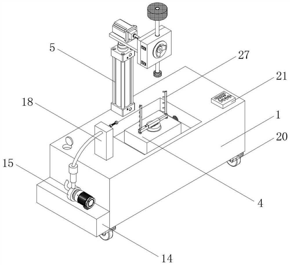
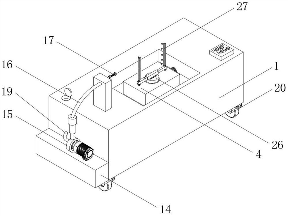
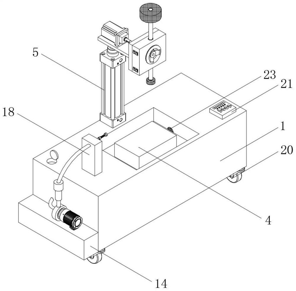
[0027] The present invention provides such Figure 1-6 A grinding machine tool for metal processing as shown, including a machine tool processing table 1, the back of the top of the machine tool processing table 1 is fixedly connected with an electric cylinder 5, the top of the electric cylinder 5 is fixedly connected with the middle of the bottom end of the square connecting plate 6, and the electric cylinder The model of 5 is TN20-50, the electric cylinder 5...


PUM


Abstract

The invention discloses a grinding machine tool for metal machining. The grinding machine tool comprises a machine tool machining table, wherein an electric cylinder is fixedly connected to the back face of the top end of the machine tool machining table; the top end of the electric cylinder is fixedly connected to the middle of the bottom end of a square connecting plate; an electric rotating machine is fixedly connected to one side of the top end of the square connecting plate; and one end of the output end of the electric rotating machine is fixedly connected to one end of a rotating shaft. The electric cylinder is started, so that a first grinding wheel and a second grinding wheel on an electric grinding machine are lifted, then the electric rotating machine is started, the first grinding wheel and the second grinding wheel on the electric grinding machine can rotate around the rotating shaft, finally, the electric grinding machine is started, and the first grinding wheel or the second grinding wheel can be used for comprehensively machining the surface of metal; and the problems that the grinding wheel of the grinding machine is fixed to the grinding machine tool, the grinding angle is difficult to adjust according to the structure of the metal surface, and the metal machining efficiency of machining personnel is affected are solved.

Description

technical field [0001] The invention relates to the technical field of metal processing, in particular to a grinding machine tool for metal processing. Background technique [0002] Metal processing refers to the production activities of human beings to process metal elements or materials with metal characteristics mainly composed of metal elements. Metal processing is referred to as metalworking. Large parts such as bridges and ships, as well as tiny components of engines, jewelry, and watches. It is widely used in different fields such as science, industry, art, handicraft, etc. Metal processing requires the use of grinding machines to grind and polish metal. [0003] Grinding is a mechanical processing method for removing materials. It refers to a processing method that uses abrasives and abrasive tools to remove excess material on a workpiece. Grinding processing is one of the most widely used material removal methods. Processing, the processing amount is small and the...

Claims


Application Information

Patent Timeline
IPC IPC(8): B24B19/00B24B27/00B24B47/12B24B47/16B24B47/22B24B55/02B24B55/06B24B55/12
CPCB24B19/00B24B27/0007B24B27/0076B24B47/12B24B47/16B24B47/22B24B27/0084B24B55/06B24B55/12B24B55/02
Inventor 李衍成
Owner 浏阳市银丰机械制造有限公司
Learn More