Water-cooling power device and monitoring equipment

A power device and water-cooling technology, which is applied in the construction of electrical equipment components, modification with liquid cooling, cooling/ventilation/heating transformation, etc., can solve the problems of main chip crash, equipment damage, and high heat generation of the main chip, etc.

Pending Publication Date: 2021-07-30
软智电子有限公司
View PDF0 Cites 0 Cited by
  • Summary
  • Abstract
  • Description
  • Claims
  • Application Information

AI Technical Summary

Problems solved by technology

[0002] At present, most of the existing surveillance cameras do not have a good cooling function. For surveillance cameras used in high-temperature areas, the equipment is often damaged due to the ambient temperature exceeding the monitoring equipment’s own industrial standards, and the use effect is poor.
When the monitoring equipment works in a high-temperature environment with an ambient temperature above 100°C, the temperature of its main chip may exceed the maximum operating temperature and cause problems such as crash
Most of the existing cooling schemes for the main chip of monitoring equipment are cooled by the built-in radiator of the monitoring equipment. When the built-in radiator of the monitoring equipment is at a high temperature above 100°C, the heat cannot be discharged from the monitoring equipment, and the temperature of the main chip itself is greatly increased. When the temperature of the main chip continues to rise to more than 120°C due to high-temperature heating in the upper environment, the main chip will stop working and the monitoring equipment will crash

Method used


Image

  • Water-cooling power device and monitoring equipment
  • Water-cooling power device and monitoring equipment
  • Water-cooling power device and monitoring equipment

Examples


Embodiment Construction

[0047] The present invention will be further described in detail below in conjunction with the accompanying drawings and embodiments. It should be understood that the specific embodiments described here are only used to explain the present invention, but not to limit the present invention. In addition, it should be noted that, for the convenience of description, only some structures related to the present invention are shown in the drawings but not all structures.

[0048] In the description of the present invention, unless otherwise clearly specified and limited, the terms "connected", "connected" and "fixed" should be understood in a broad sense, for example, it can be a fixed connection, a detachable connection, or an integrated ; It can be a mechanical connection or an electrical connection; it can be a direct connection or an indirect connection through an intermediary, and it can be the internal communication of two components or the interaction relationship between two ...


PUM


Abstract

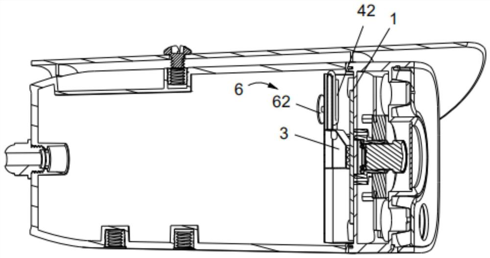
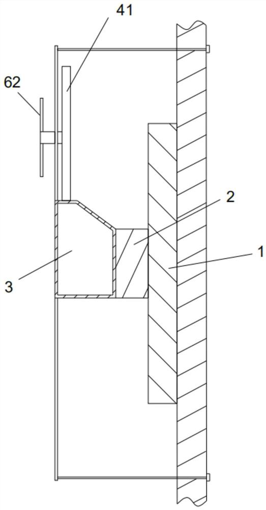
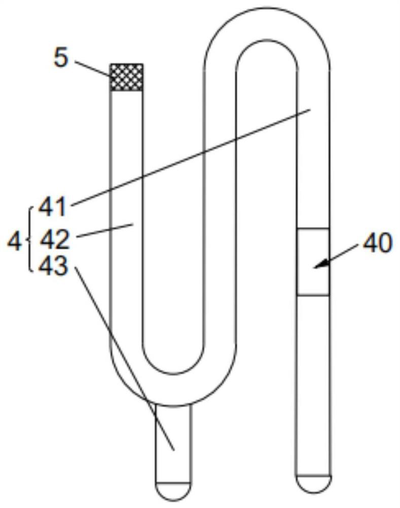
The invention relates to the technical field of monitoring equipment, and discloses a water-cooling power device and monitoring equipment. The water-cooling power device comprises a cooling box, a cooling pipe and an air-cooling assembly. One face of the cooling box is attached to a cooled object, cooling liquid is contained in the cooling box, one end of the cooling pipe communicates with the cooling box, the other end of the cooling pipe is arranged in a sealed mode, and two opposite installation through holes are formed in the cooling pipe; the cooling liquid can be vaporized in the cooling box to form steam and flow along the cooling pipe, one part of the air cooling assembly is rotatably arranged in the two mounting through holes in a penetrating mode, the other part of the air cooling assembly is rotatably arranged outside the cooling pipe, and the steam can drive the air cooling assembly to rotate. According to the water-cooling power device, the main chip is cooled, and the energy consumption is low. The monitoring equipment comprises the water-cooling power device, and the situation that the monitoring equipment crashes due to the fact that the temperature of a main chip of the monitoring equipment is too high can be effectively avoided.

Description

technical field [0001] The invention relates to the technical field of water cooling power, in particular to a water cooling power device and monitoring equipment. Background technique [0002] At present, most of the existing surveillance cameras do not have a good cooling function. For surveillance cameras used in high-temperature areas, the equipment is often damaged because the ambient temperature exceeds the industrial standard of the surveillance equipment itself, and the use effect is poor. When the monitoring equipment works in a high-temperature environment with an ambient temperature above 100°C, the temperature of its main chip may exceed the maximum operating temperature, resulting in crashes and other problems. Most of the existing cooling schemes for the main chip of monitoring equipment are cooled by the built-in radiator of the monitoring equipment. When the built-in radiator of the monitoring equipment is at a high temperature above 100°C, the heat cannot be...

Claims


Application Information

Patent Timeline
Patent Type & Authority Applications(China)
IPC IPC(8): H05K7/20G03B17/55H04N5/225
CPCH05K7/20309H05K7/20327H05K7/20172G03B17/55H04N23/50
Inventor 杨荣华张田圆
Owner 软智电子有限公司
Why Eureka
Try Eureka