Foundation pit dewatering and drainage method for reducing influence on surrounding buildings

A technology for buildings and foundation pits, applied in construction, infrastructure engineering, etc., can solve the problems of surface deformation, narrow working surface, restricted working surface, etc. Effect

Pending Publication Date: 2021-07-30
CHINA FIRST METALLURGICAL GROUP
View PDF8 Cites 0 Cited by
  • Summary
  • Abstract
  • Description
  • Claims
  • Application Information

AI Technical Summary

Problems solved by technology

[0003] However, in urban underground pipe network reconstruction projects, since there are a large number of buildings on both sides of the road, and the underground pipe network is usually set on both sides of the road, it is often difficult to dewater the foundation pit of the pipe network due to a large amount of emptying of groundwater. Cause the ground surface to deform, thereby causing the surrounding buildings to be pulled apart, causing significant economic losses; moreover, because the width of the foundation pit is limited by the buildings on both sides, the working surface usually left inside the foundation pit is very narrow, and at the same time, In order to drain the precipitation on the surface, it is usually necessary to set drainage ditches on both sides of the foundation pit, which further limits the working surface inside the foundation pit.

Method used


Image

  • Foundation pit dewatering and drainage method for reducing influence on surrounding buildings
  • Foundation pit dewatering and drainage method for reducing influence on surrounding buildings
  • Foundation pit dewatering and drainage method for reducing influence on surrounding buildings

Examples


Embodiment Construction

[0023] The following will clearly and completely describe the technical solutions in the embodiments of the present invention with reference to the accompanying drawings in the embodiments of the present invention. Obviously, the described embodiments are only some, not all, embodiments of the present invention. Based on the embodiments of the present invention, all other embodiments obtained by persons of ordinary skill in the art without creative efforts fall within the protection scope of the present invention.

[0024] It should be noted that, in the case of no conflict, the embodiments of the present invention and the features in the embodiments can be combined with each other.

[0025] The present invention will be further described below in conjunction with the accompanying drawings and specific embodiments, but not as a limitation of the present invention.

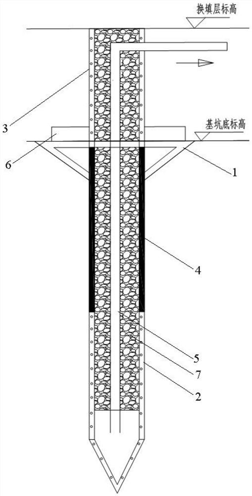
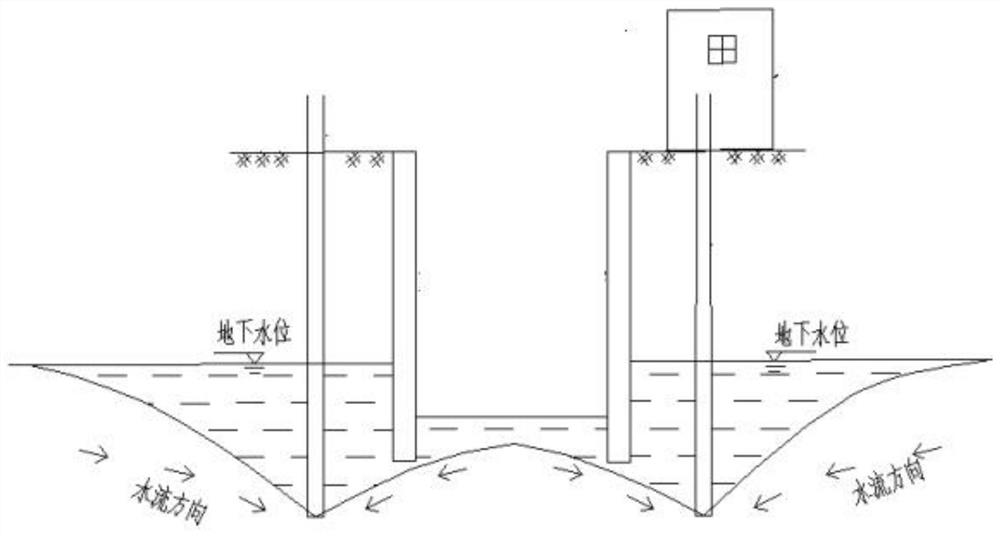
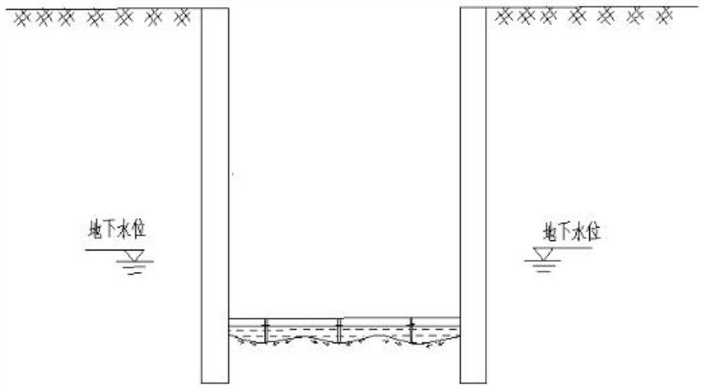
[0026] Provided in this embodiment is a foundation pit dewatering and drainage method that reduces the impact on...


PUM


Abstract

The invention discloses a foundation pit dewatering and drainage method for reducing influence on surrounding buildings. The method includes the steps that waterproof cloth is fully paved at the bottom of a foundation pit according to the size of a base to form a waterproof layer; a steel pipe is taken, water inlet holes are formed in the peripheral walls of the bottom and the upper portion of the steel pipe, a first water inlet area and a second water inlet area are formed, and a floral tube is obtained; the floral tube is inserted into the foundation pit, a water conveying hose is conveyed to the bottom of the floral tube, the other end of the water conveying hose is led out of the floral tube, and a pressing disc is installed on the floral tube; a filter material is backfilled, an inverted filter layer is laid according to design requirements, the other end of the water conveying hose is communicated with a drainage main pipe, a water pump is opened to start drainage, and the drainage main pipe in the foundation pit is dismantled and the water pump is removed after building construction in the foundation pit is completed; and the steps are repeated until all construction is completed. According to the foundation pit dewatering and drainage method for reducing the influence on the surrounding buildings, the influence range of foundation pit dewatering is only limited in the foundation pit, so that the parabolic effect of dewatering is greatly reduced, and finally, damage to underground water resources is greatly reduced while safety of the surrounding buildings is guaranteed.

Description

technical field [0001] The invention relates to a drainage method, in particular to a foundation pit drainage method which reduces the impact on surrounding buildings. Background technique [0002] Excavation of foundation pits is involved in all kinds of engineering construction, and in many areas with developed water systems, the groundwater level is higher than the bottom of the foundation pits, so in order to meet the safety of the foundation pits during the construction Set up a large number of dewatering wells around the foundation pit before digging, and carry out 24-hour uninterrupted dewatering during construction. [0003] However, in urban underground pipe network reconstruction projects, since there are a large number of buildings on both sides of the road, and the underground pipe network is usually set on both sides of the road, it is often difficult to dewater the foundation pit of the pipe network due to a large amount of emptying of groundwater. Cause the g...

Claims


Application Information

Patent Timeline
Patent Type & Authority Applications(China)
IPC IPC(8): E02D19/10
CPCE02D19/10
Inventor 蒋凯田雨鑫
Owner CHINA FIRST METALLURGICAL GROUP
Why Eureka
Try Eureka