A workpiece surface treatment process and treatment equipment
A technology for processing equipment and workpiece surfaces, applied in metal processing equipment, welding equipment, welding equipment, etc., can solve the problems of low processing efficiency of ring plate workpieces, complex fixture design, unfavorable use by factory workers, etc.
- Summary
- Abstract
- Description
- Claims
- Application Information
AI Technical Summary
Problems solved by technology
Method used
Image
Examples
Embodiment 1
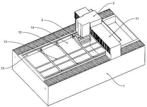
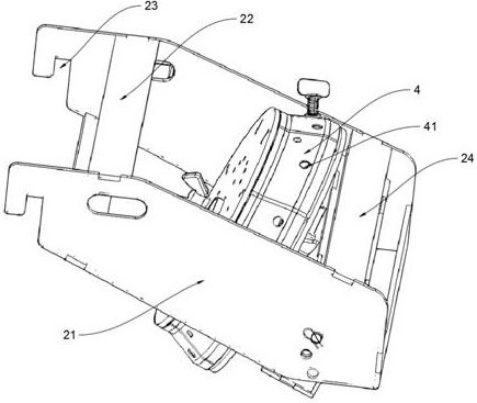
[0028] Such as figure 1 , figure 2 As shown, a workpiece surface treatment equipment includes a base support 1, the upper end of the base support 1 is connected with a moving support 11 that can move along a straight line, and the surface of the moving support 11 is connected with a moving support that can move along a straight line. The laser part 3, the inside of the base bracket 1 is provided with a number of vertical plate parts 12 and a number of horizontal plate parts 13, the vertical plate parts 12 and the horizontal plate parts 13 are surrounded by a wall-mounted groove 14, and the wall-mounted groove 14 is placed with a connecting frame 2, and the ring plate workpiece 4 is fixed on the surface of the connecting frame 2. The laser part 3 processes the ring plate workpieces 4 in several wall hanging grooves 14 through its own movement and the movement of the moving support 11. .
[0029] In this embodiment, both the mobile support 1 and the laser part 3 can use the e...
Embodiment 2
[0034] Such as figure 1 , figure 2 As shown, a workpiece surface treatment equipment includes a base support 1, the upper end of the base support 1 is connected with a moving support 11 that can move along a straight line, and the surface of the moving support 11 is connected with a moving support that can move along a straight line. The laser part 3, the inside of the base bracket 1 is provided with a number of vertical plate parts 12 and a number of horizontal plate parts 13, the vertical plate parts 12 and the horizontal plate parts 13 are surrounded by a wall-mounted groove 14, and the wall-mounted groove 14 is placed with a connecting frame 2, and the ring plate workpiece 4 is fixed on the surface of the connecting frame 2. The laser part 3 processes the ring plate workpieces 4 in several wall hanging grooves 14 through its own movement and the movement of the moving support 11. .
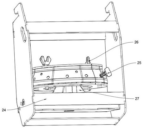
[0035] Such as figure 2 and image 3 As shown, further, the connecting frame 2 inclu...
Embodiment 3
[0041] Such as figure 1 , figure 2 As shown, a workpiece surface treatment equipment includes a base support 1, the upper end of the base support 1 is connected with a moving support 11 that can move along a straight line, and the surface of the moving support 11 is connected with a moving support that can move along a straight line. The laser part 3, the inside of the base bracket 1 is provided with a number of vertical plate parts 12 and a number of horizontal plate parts 13, the vertical plate parts 12 and the horizontal plate parts 13 are surrounded by a wall-mounted groove 14, and the wall-mounted groove 14 is placed with a connecting frame 2, and the ring plate workpiece 4 is fixed on the surface of the connecting frame 2. The laser part 3 processes the ring plate workpieces 4 in several wall hanging grooves 14 through its own movement and the movement of the moving support 11. .
[0042] Such as figure 2 and image 3 As shown, further, the connecting frame 2 inclu...
PUM
 Abstract
Description
Claims
Application Information
 - Generate Ideas
- Intellectual Property
- Life Sciences
- Materials
- Tech Scout
- Unparalleled Data Quality
- Higher Quality Content
- 60% Fewer Hallucinations
Browse by: Latest US Patents, China's latest patents, Technical Efficacy Thesaurus, Application Domain, Technology Topic, Popular Technical Reports.
© 2025 PatSnap. All rights reserved.Legal|Privacy policy|Modern Slavery Act Transparency Statement|Sitemap|About US| Contact US: help@patsnap.com


