
Additive and subtractive composite manufacturing part deformation prediction and control method and equipment

A control method and technology of adding and subtracting materials, applied in computer-aided design, design optimization/simulation, special data processing applications, etc., can solve the problems of simulation parts not being too large, long calculation time, large calculation amount, etc., to reduce heat The effect of deformation amount, speed up calculation, and simplification of calculation process

Active Publication Date: 2021-07-23
XI AN JIAOTONG UNIV +1
View PDF3 Cites 5 Cited by
  • Summary
  • Abstract
  • Description
  • Claims
  • Application Information

AI Technical Summary

Problems solved by technology

[0005] The purpose of the present invention is to provide a method for predicting and controlling the deformation of a composite manufacturing part by adding and subtracting materials to solve the problems that the simulated part cannot be too large, the calculation time is long, and the calculation amount is large when the software simulation is used to predict the deformation of the part in the above-mentioned prior art. The equipment can quickly and accurately obtain the overall temperature field-stress field-displacement field, and then quickly correct the inverse deformation model

Method used


Image

  • Additive and subtractive composite manufacturing part deformation prediction and control method and equipment
  • Additive and subtractive composite manufacturing part deformation prediction and control method and equipment
  • Additive and subtractive composite manufacturing part deformation prediction and control method and equipment

Examples


Embodiment Construction

[0049] The present invention will be further described in detail below in conjunction with the accompanying drawings and embodiments.

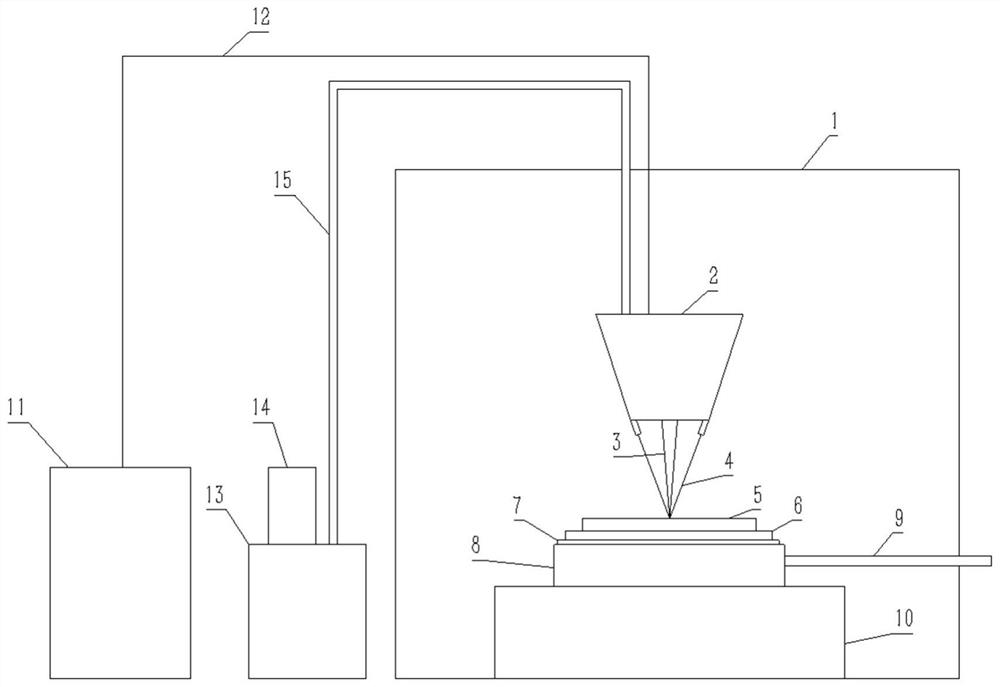
[0050] see figure 1 The coaxial powder-feeding laser melting additive manufacturing equipment includes an inert gas protection glove box 1, a laser cladding head 2 for spraying a laser beam 3 and metal powder 4, a substrate 6 for placing a component 5, and a heat-conducting silica gel 7 arranged under the substrate 6 and Heat conduction copper plate 8, heating liquid conduit 9, workbench 10, laser 11, optical fiber 12, powder feeder 13, powder feed barrel 14, powder feed pipe 15.

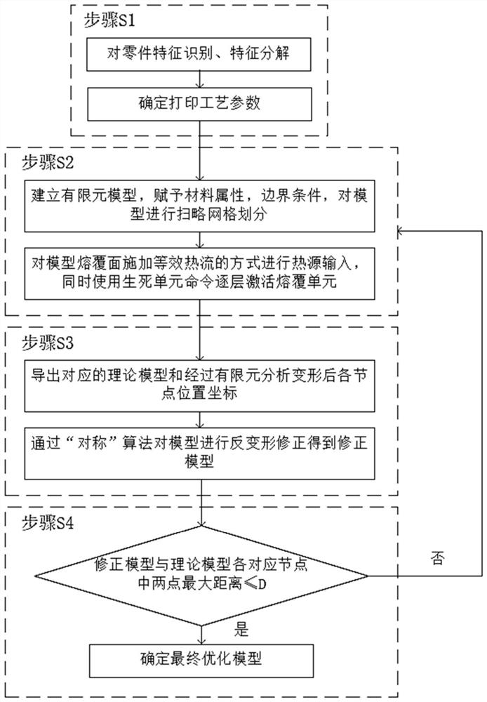
[0051] see figure 2 , a method for predicting and controlling the deformation of additive and subtractive composite manufacturing parts, comprising the following steps:

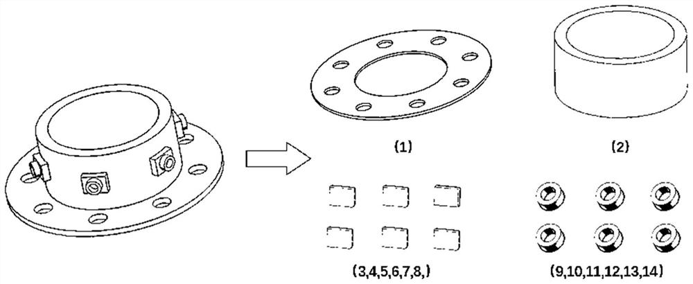
[0052] Step S1: Perform the following steps on the parts to be predicted image 3 The feature recognition shown is to extract the main features of the parts, decompose the features of the parts...


PUM


Abstract

The invention discloses an additive and subtractive composite manufacturing part deformation prediction and control method and equipment. The method comprises conducting feature recognition and feature decomposition on a target part model, and determining printing parameters; performing finite element thermal coupling analysis of equivalent loading on the model; performing model reversible deformation optimization design according to a simulation result; and determining an optimized final part structure model in an iteration mode. According to the method, a method of combining unit-by-unit activation and Gaussian moving heat source commonly adopted at present is converted into surface heat flow loading of layer-by-layer life and death unit activation in an energy equivalent mode. In the simulation process, birth and death units are used for simulation, all the units are killed firstly, namely, the rigidity is changed into 0, and then the rigidity is activated to be changed into a'birth 'state. Compared with other current life-death unit analog simulation additive manufacturing methods, the method has the advantages that the calculation process can be simplified, the calculation speed can be increased, overall simulation of large parts can be achieved, and an overall temperature field-stress field-displacement field can be obtained quickly.

Description

technical field [0001] The invention belongs to the field of high-precision mechanical manufacturing, and in particular relates to a method and equipment for predicting and controlling the deformation of parts in composite manufacturing of additive and subtractive materials. Background technique [0002] When using the powder-feeding laser cladding technology for metal additive and subtractive composite manufacturing, since the laser needs to be introduced to manufacture the parts, the parts will generate thermal stress and cause thermal deformation when heated. For parts with high precision requirements and large size requirements used in aerospace and other fields, the deformation of the parts must be predicted and controlled, which can reduce the scrap rate, thereby saving production costs and shortening the research and development cycle. [0003] Since the experimental method consumes a lot of time and money, and the deformation results can only be obtained after the ad...

Claims


Application Information

Patent Timeline
Patent Type & Authority Applications(China)
IPC IPC(8): G06F30/17G06F30/23G06F113/10G06F119/08G06F119/14
CPCG06F30/17G06F30/23G06F2119/08G06F2119/14G06F2113/10Y02P10/25
Inventor 薛飞郭张远张旗
Owner XI AN JIAOTONG UNIV
Learn More