
Metal energy dissipation type bridge anti-falling beam device and mounting method thereof

An anti-falling beam and energy-consuming technology, which is applied in bridges, bridge parts, bridge construction, etc., can solve problems such as ineffective control of collisions between main girders, failure to meet earthquake resistance requirements, and poor effect of anti-falling beams. Simple, easy to replace, easy to install

Pending Publication Date: 2021-07-23
BEIJING UNIV OF TECH
View PDF11 Cites 0 Cited by
  • Summary
  • Abstract
  • Description
  • Claims
  • Application Information

AI Technical Summary

Problems solved by technology

The existing anti-fall beam devices have poor anti-fall beam effects and cannot effectively control the collision between the main beams, and the construction is complicated, and it is not easy to replace after the earthquake, which cannot meet the earthquake resistance requirements

Method used


Image

  • Metal energy dissipation type bridge anti-falling beam device and mounting method thereof
  • Metal energy dissipation type bridge anti-falling beam device and mounting method thereof
  • Metal energy dissipation type bridge anti-falling beam device and mounting method thereof

Examples


Embodiment Construction

[0027] The specific embodiment of a kind of metal energy consumption type anti-falling beam device of the present invention is described below in conjunction with accompanying drawing:

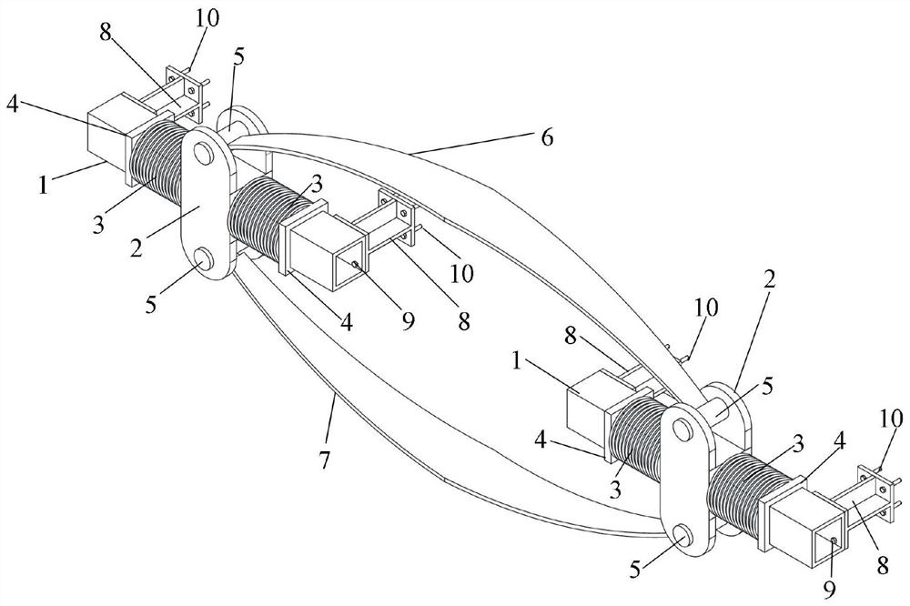
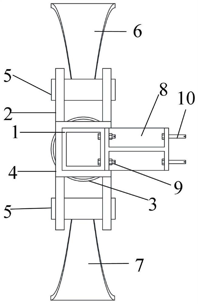
[0028] Such as figure 1 As shown, a metal energy-dissipating anti-fall beam device includes a sliding part and an energy-dissipating part, wherein the sliding part is composed of a core square steel pipe 1, an assembled metal slider 2, a spring 3, a spring baffle 4, and a pin 5 , the sliding parts are symmetrically distributed. The energy-dissipating parts consist of an upper arc-shaped metal energy-dissipating plate 6 and a lower arc-shaped metal energy-dissipating plate 7 . The connector 8 is connected with the core square steel pipe 1 through the first bolt 9, and the whole metal energy-consuming anti-fall beam device is connected with the main beams 13, 14 on the left and right sides through the second bolt 10 or with the main beam 13 (14 ) is connected with the cover beam 16.

[0029] ...


PUM


Abstract

The invention discloses a metal energy dissipation type bridge anti-beam-falling device and a mounting method thereof. The metal energy dissipation type bridge anti-beam-falling device comprises core square steel pipes arranged on main beams on the left side and the right side, metal sliding blocks, springs, spring baffles, pin shafts, reserved bolt hole connecting pieces, first connecting bolts, second connecting bolts. and an upper arc-shaped metal energy consumption plate and a lower arc-shaped metal energy consumption plate which are arranged in the middle. The metal sliding blocks are sleeved outside the center positions of the core square steel pipes, two springs are respectively sleeved outside two sides of the metal sliding blocks, the other ends of the springs are contacted with spring limiting plates, and the limiting plates are fixed on the core steel pipes. The two ends of the upper arc-shaped metal energy consumption plate are welded to the upper pin shafts of the sliding parts on the left side and the right side correspondingly. In a normal use state, the telescopic deformation of the main beam caused by temperature change is adapted through the sliding of the metal sliding blocks and the elastic deformation of the metal springs; the mechanical property of a metal material is fully exerted, the energy dissipation capacity is high and stable, installation is easy, and replacement is easy after an earthquake.

Description

technical field [0001] The invention belongs to the technical field of anti-seismic bridges, and in particular relates to a metal energy-consuming bridge anti-drop beam device and an installation method thereof. Background technique [0002] The girder body and the substructure of small and medium-span beam bridges are usually connected by plate rubber bearings. The beam body is placed directly on the support, and there is no anchoring measure between the bearing, the pier top and the contact surface of the beam body. When an earthquake comes, This connection method is extremely easy to cause damage to the falling beam and collision between the main beams. In order to prevent falling beam damage, an anti-fall beam device is usually used to prevent falling beam damage. The existing anti-fall beam devices have poor anti-fall beam effects and cannot effectively control the collision between the main beams, and the construction is complicated, and it is not easy to replace afte...

Claims


Application Information

Patent Timeline
Patent Type & Authority Applications(China)
IPC IPC(8): E01D19/00E01D19/02E01D21/00
CPCE01D19/00E01D19/02E01D21/00
Inventor 贾俊峰李茂昌白玉磊杜修力许坤
Owner BEIJING UNIV OF TECH
Learn More