
A double-t-shaped core lattice type anti-buckling bracing member

A lattice type and glyph technology, which is applied to building components, earthquake resistance, etc., can solve the problems of increasing component processing and transportation costs, failing to give full play to energy consumption capacity, and increasing self-weight.

Inactive Publication Date: 2016-06-15
TSINGHUA UNIV
View PDF7 Cites 0 Cited by
  • Summary
  • Abstract
  • Description
  • Claims
  • Application Information

AI Technical Summary

Problems solved by technology

However, with the ever-increasing requirements for cross-section types and super-large support force in engineering, the traditional integral section buckling-resistant brace has the following shortcomings: (1) The section size of the large-tonnage buckling-resistant brace must be made very large, and its The self-weight will increase exponentially, increasing the cost of component processing and transportation; (2) With the increase of the self-weight of the anti-buckling support components, the earthquake will bear greater earthquake action, forming a vicious circle; (3) due to the Due to the inevitable eccentricity at the end nodes or the rigid connection of the nodes, the anti-buckling support members in the frame structure will bear a certain additional bending moment
Studies have shown that the existence of this additional bending moment may lead to premature failure of the buckling-resistant brace members, which cannot fully exert their energy dissipation capacity

Method used


Image

  • A double-t-shaped core lattice type anti-buckling bracing member
  • A double-t-shaped core lattice type anti-buckling bracing member
  • A double-t-shaped core lattice type anti-buckling bracing member

Examples


Embodiment Construction

[0020] Attached below Figure 1-7 , to describe in detail the specific embodiments of the present invention.

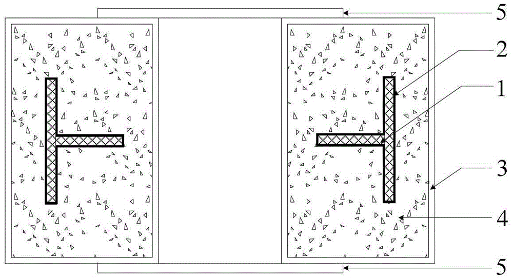
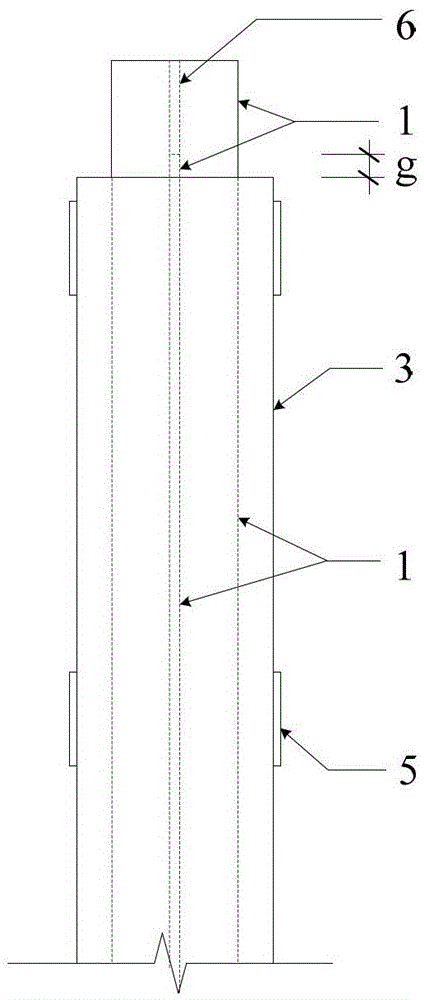
[0021] Such as Figure 1~3 As shown, a double T-shaped core lattice buckling-resistant support member includes the following components:

[0022] 1——T-shaped core components, two in total;

[0023] 2——No bonding material;

[0024] 3—constrained rectangular steel pipes, two in total;

[0025] 4 - Concrete;

[0026] 5——Steel panel;

[0027] 6—end ribs;

[0028] Such as figure 1 , 5 , 6, the buckling-resistant bracing member of the double T-shaped core lattice structure is formed by two buckling-resistant limbs connected by several steel panels 5 distributed along the longitudinal direction; each limb is a T-shaped core and the rectangular steel tube concrete Constrained anti-buckling bracing member, composed of T-shaped inner core member 1, unbonded material 2, constrained rectangular steel pipe 3, and inner poured concrete 4;

[0029] Such as Figure 5 , 6 ...


PUM


Abstract

A latticed anti-buckling supporting member provided with double T-shaped cores is formed by connecting two anti-buckling branches through a plurality of steel lattice plates respectively, wherein each anti-buckling branch supporting member adopts a T-shaped core member and a rectangular restrained concrete filled steel tube; long edges of the two branches are arranged in parallel at an appropriate interval, the latticed member is formed by connecting a plurality of longitudinally distributed steel lattice plates, the steel lattice plates are in welded connection with short edges of the branches through trihedral fillet welds, and the edge of the branches are the short edges of the rectangular restrained steel tubes. Ends of the two T-shaped core members extend out of the rectangular restrained steel tubes, and a ribbed plate is welded between outwards extending plates of the two cores, so that an H-shaped section is formed and can be connected with a frame member through a high-strength bolt and a connecting plate. The latticed section can increase the inertia moment of a whole section of the anti-buckling supporting member and the whole anti-bending stiffness and is particularly suitable for the design of a large-tonnage anti-buckling supporting member, a supporting end and the frame member are conveniently connected, and the energy-consuming capacity of the branches can be fully exerted under the action of an additional eccentric bending moment.

Description

technical field [0001] The invention relates to a novel buckling-resistant energy-dissipating support member, which belongs to the technical field of structural engineering. technical background [0002] Buckling-resistant bracing members are generally composed of two parts: the inner core member and the outer restraint member. Under the action of small earthquakes, the inner core of the buckling-resistant support members remains elastic, providing sufficient lateral stiffness for the main structure; Very full, fully energy-dissipating and shock-absorbing, and can provide sufficient protection for the main frame. The anti-buckling support member has the dual functions of "energy dissipation" and "support", and has excellent energy dissipation and shock absorption performance, and can be widely used in the reinforcement of new structures and existing structures. So far, more than 300 buildings in Japan and no less than 30 buildings under construction and in the United State...

Claims


Application Information

Patent Timeline
Patent Type & Authority Patents(China)
IPC IPC(8): E04B1/98
Inventor 郭彦林张博浩窦超姜子钦张旭乔刘锋
Owner TSINGHUA UNIV
Learn More