Minimally invasive scalp retractor
A retractor and scalp technology, applied in the field of minimally invasive scalp retractors, can solve the problems of lack of devices for lifting the scalp, etc., and achieve the effects of reducing the incidence of infection, improving surgical efficiency, and reducing postoperative scars
- Summary
- Abstract
- Description
- Claims
- Application Information
AI Technical Summary
Problems solved by technology
Method used
Image

Examples
Embodiment 1
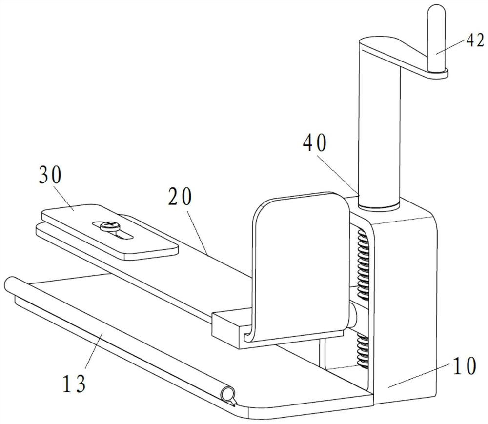
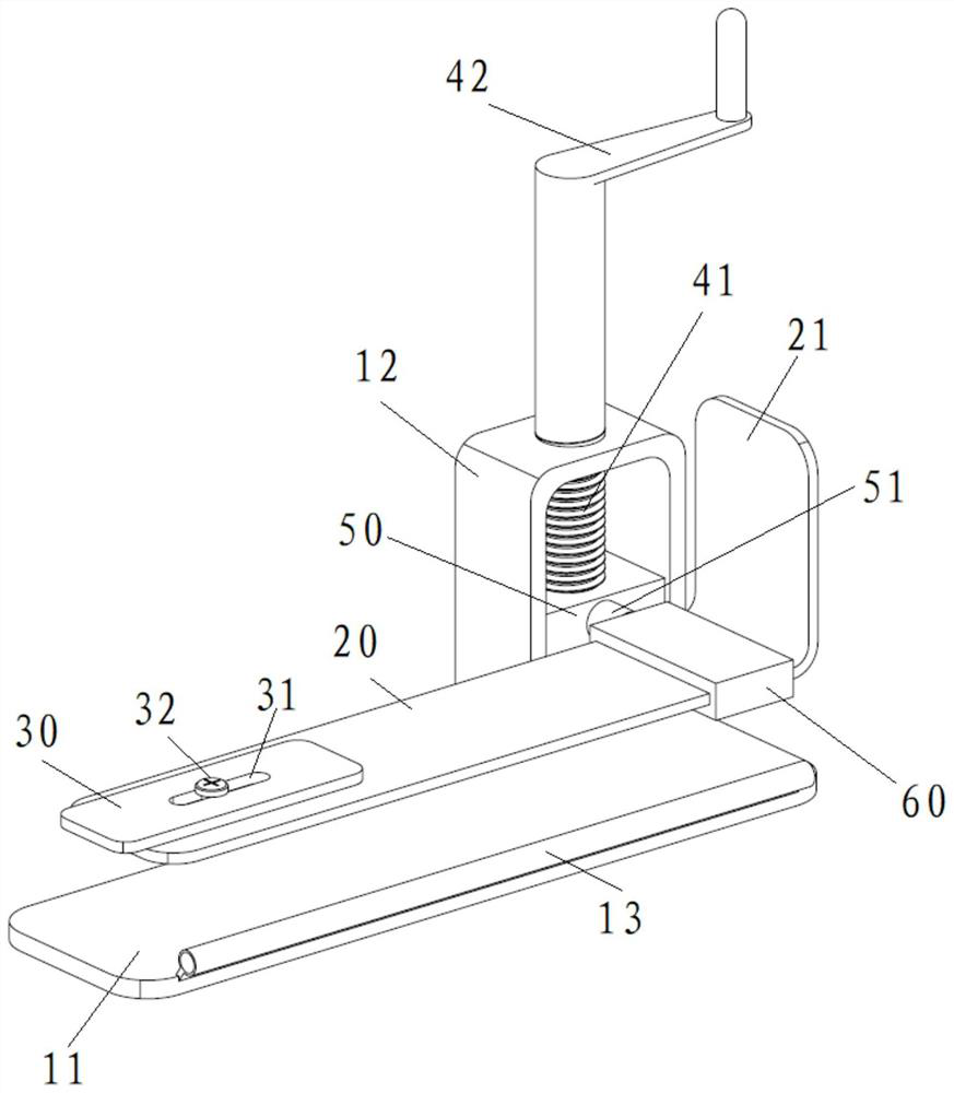
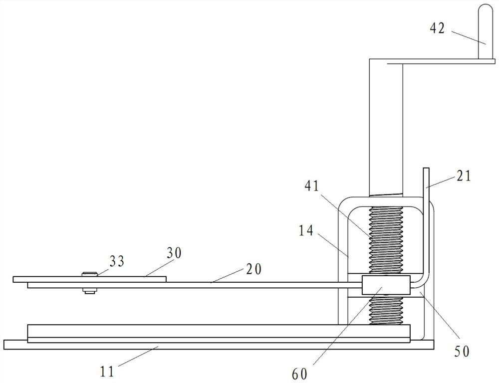
[0048] Figure 1~3 Respectively, a structural representation of a minimally invasive scalp retractor in an embodiment of the present application Figure 1 , structural representation Figure II and a front view, such as Figure 1~3 As shown, the retractor includes a base 10 , a plectrum 20 and an adjustment part 40 .
[0049] The first end of the dial 20 is arranged on the base 10 so as to reciprocate along the first direction, and the second end of the dial 20 is rotatably and lockably connected with a dial 30 so that it can be adjusted The inclination direction of the dial 30 on the dial 20; the adjustment part 40 is connected with the dial 20 to drive the dial 20 to move on the base 10, thereby adjusting the dial 20 the position in the first direction.
[0050] When using the retractor, the patient lies flat so that the plectrum 20 is located on one side of the patient's head, then the first direction is the up-down direction, that is, the vertical direction, and the se...
Embodiment 2
[0066] The difference between this embodiment and Embodiment 1 is that: the connection method between the sleeve 51 and the rotating shaft 61 is different. In this embodiment, the sleeve 51 and the rotating shaft 61 are connected by threads, as follows:
[0067] Such as Figure 6 , 7 As shown, the sleeve 51 is provided with an internal thread 53, the rotating shaft 61 is provided with an external thread 63, and the external thread 63 is engaged with the internal thread 53, and the external thread section on the rotating shaft 61 (set The length of the part of the external thread) is longer than the length of the internal thread section (the part where the internal thread is provided) on the sleeve 51, so that the sleeve 51 and the shaft 61 pass through the internal thread 53 and the After the external thread 63 is screwed and fitted, the rotating shaft 61 can still rotate with the sleeve 51, similar to the jack, so as to realize the stepless adjustment of the inclination angl...
Embodiment 3
[0070] The difference between this embodiment and Embodiment 1 is that the locking method of the sleeve 51 and the rotating shaft 61 is different. In this embodiment, the sleeve 51 and the rotating shaft 61 are locked by the second screw 70, specifically as follows:
[0071] The rotating shaft 61 is rotatably arranged in the sleeve 51, and the sleeve 51 is provided with a radial hole, and the inner end of the second screw 70 passes through the radial hole and abuts against the rotating shaft. 61 to lock the rotating shaft 61 in the sleeve 51, so as to realize the stepless adjustment of the inclination angle of the plectrum 20, and any angle can be adjusted, which is more practical.
PUM
 Abstract
Description
Claims
Application Information
 - Generate Ideas
- Intellectual Property
- Life Sciences
- Materials
- Tech Scout
- Unparalleled Data Quality
- Higher Quality Content
- 60% Fewer Hallucinations
Browse by: Latest US Patents, China's latest patents, Technical Efficacy Thesaurus, Application Domain, Technology Topic, Popular Technical Reports.
© 2025 PatSnap. All rights reserved.Legal|Privacy policy|Modern Slavery Act Transparency Statement|Sitemap|About US| Contact US: help@patsnap.com