Novel multifunctional water gate
A multi-functional, sluice technology, applied in water conservancy projects, cleaning of open water surfaces, sea area engineering, etc., can solve the problems of automatic reinforcement and fixation, single function, and inability to collect garbage, etc., to achieve the effect of strengthening the sealing effect and strengthening the fixing effect
- Summary
- Abstract
- Description
- Claims
- Application Information
AI Technical Summary
Problems solved by technology
Method used
Image
Examples
Embodiment 1
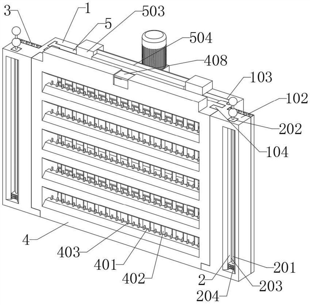
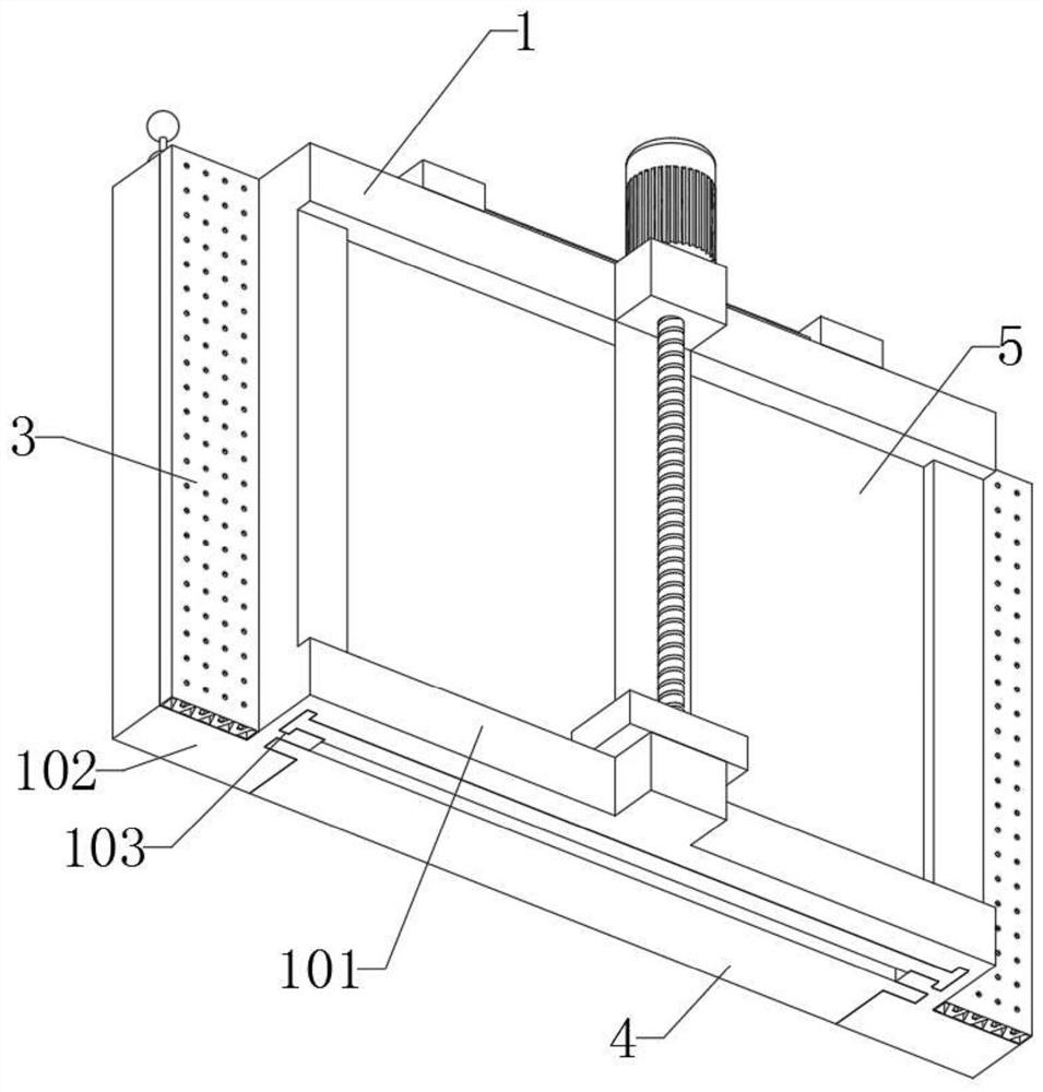
[0074] The invention provides a new type of multifunctional water gate, which includes a main body 1; the main body 1 is a T-shaped structure, and a motor is installed in the middle of the main body 1, and a round hole is arranged in the middle of the main body 1, and the shaft of the motor is inserted into the round hole. , the shaft of the motor is a cylindrical structure protruding in the middle, the outside of the shaft is provided with threads, the front end of the side piece 102 of the main body 1 is provided with a chute 2, the rear end of the side piece 102 of the main body 1 is provided with a buffer 3, the main body 1 Collector 4 is installed at the front end of the main body 1, and the two ends of the gate 5 are embedded in the guide groove 103 of the main body 1; In order to allow water to enter better, and then push the moving part 203 to move; the buffer part 3, the buffer part 3 includes a limit mechanism, the rear end of the buffer part 3 is fixedly bonded and i...
Embodiment 2
[0080] Please refer to Figure 6 , in the second embodiment, the other structures remain unchanged, and a structural form of the buffer member 3 for buffering and auxiliary fixing is provided, aiming at solving the problem that the device will be impacted by water when in use, and the problem of displacement occurs. The buffer member 3 includes: buffer block 301, the buffer block 301 is made of rubber material, the two sides of the buffer block 301 are inclined structures, and the four buffer blocks 301 are evenly arranged inside the buffer member 3; the auxiliary groove 302, the two sides of the auxiliary groove 302 are inclined shape structure, and the auxiliary groove 302 is located in the middle of the side of the buffer block 301; the installation groove 303, the installation groove 303 is a T-shaped structure, and the upper and lower ends of the installation groove 303 are provided with four L-shaped grooves; The positioning mechanism includes: a force rod 304, the force...
Embodiment 3
[0082] Please refer to Figure 7, in the third embodiment, other structures remain unchanged, and a structure form in which the height of the collecting part 4 is adjusted to collect floating garbage is provided, aiming to solve the problems that there are more floating garbage, causing river pollution, and inability to salvage conveniently. Among them, The collecting part 4 includes: a collecting tank 401, which is an L-shaped structure, and the bottom of the collecting tank 401 is provided with an arc-shaped groove. 1 front end; block 402, block 402 is a wedge-shaped plate arranged evenly, and block 402 is arranged at the rear of collection tank 401; auxiliary block 403, auxiliary block 403 is a wedge-shaped structure, and auxiliary block 403 is evenly arranged in the collection tank The bottom of the front end of 401; side groove 404, the side groove 404 is a cylindrical structure raised in the middle, and the side groove 404 is located at the bottom ends of both sides of t...
PUM
 Abstract
Description
Claims
Application Information
 - R&D
- Intellectual Property
- Life Sciences
- Materials
- Tech Scout
- Unparalleled Data Quality
- Higher Quality Content
- 60% Fewer Hallucinations
Browse by: Latest US Patents, China's latest patents, Technical Efficacy Thesaurus, Application Domain, Technology Topic, Popular Technical Reports.
© 2025 PatSnap. All rights reserved.Legal|Privacy policy|Modern Slavery Act Transparency Statement|Sitemap|About US| Contact US: help@patsnap.com


