
Microbial incubator for microbiological detection

A technology for microbial culture and microbial detection, applied in the field of microbial culture equipment, can solve problems such as easy entry of microorganisms and sample contamination, and achieve the effects of high degree of automation, pollution reduction, and pollution probability reduction.

Active Publication Date: 2021-07-20
LUOHE MEDICAL COLLEGE
View PDF0 Cites 0 Cited by
  • Summary
  • Abstract
  • Description
  • Claims
  • Application Information

AI Technical Summary

Problems solved by technology

However, in the process of frequently opening the door, microorganisms in the environment can easily enter the incubator environment, resulting in sample contamination

Method used


Image

  • Microbial incubator for microbiological detection
  • Microbial incubator for microbiological detection
  • Microbial incubator for microbiological detection

Examples


Embodiment 1

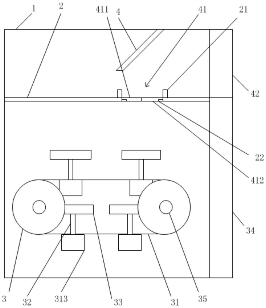
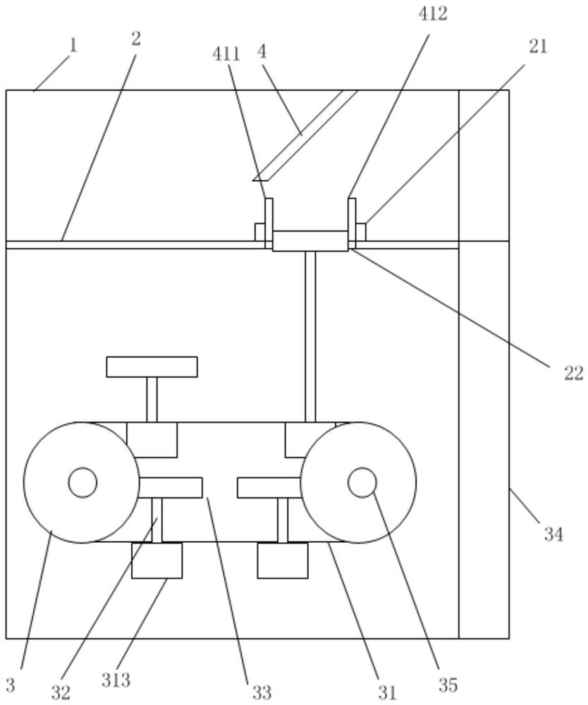
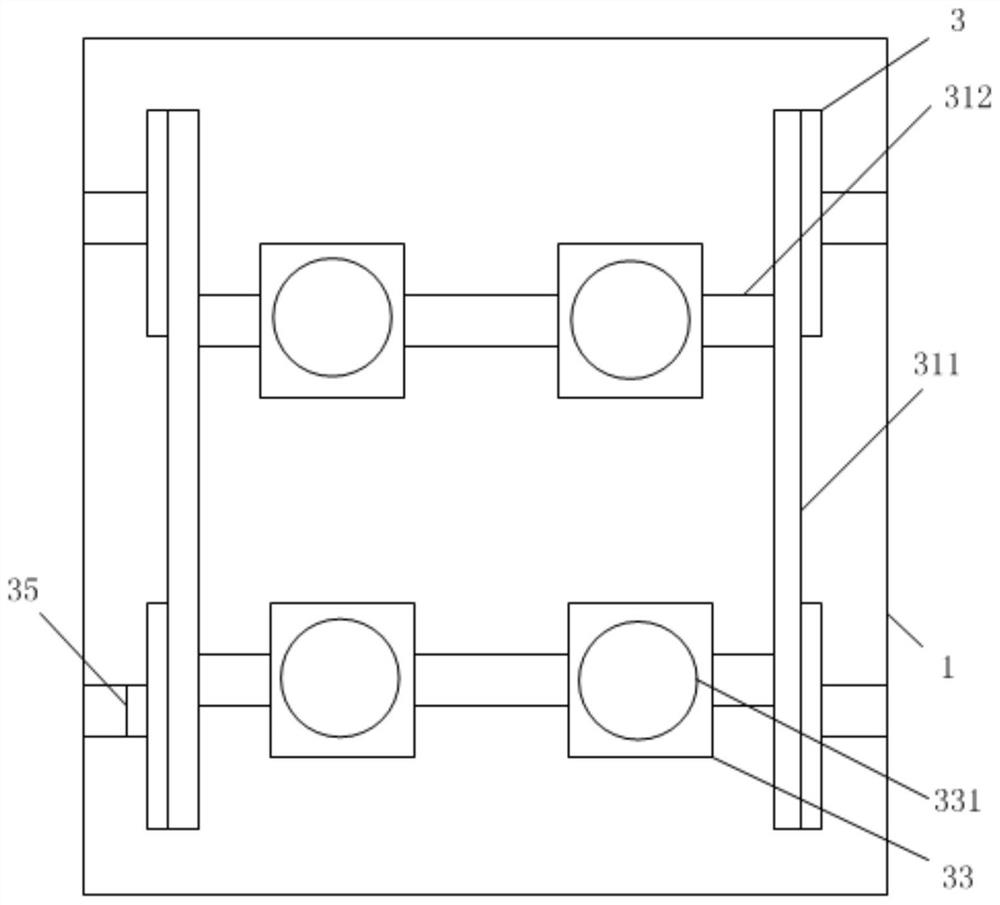
[0032] The invention provides a microbial incubator for microbial detection, see Figure 1-4 , including a box body 1, which is provided with a temperature control device and a controller; the temperature control device can refer to the structure of the incubator box body in the prior art, or the temperature control device can be set to include a heating jacket, a fan, a temperature The sensor and the controller, the controller is connected with the fan, the heater, and the temperature sensor respectively, and the temperature sensor is arranged in the cabinet 1 to measure the temperature in the cabinet, and then transmit the temperature signal to the controller, when the measured temperature exceeds the temperature in the controller The preset temperature upper limit, the controller controls the fan to work to dissipate heat. When the measured temperature is lower than the preset temperature lower limit in the controller, the controller controls the heater to work for heating. ...

Embodiment 2

[0042] A kind of microorganism incubator that is used for microorganism detection, and the structure of embodiment 1 is basically the same, the difference is that,

[0043] In this embodiment, there is no need to pre-set the "special marking position" mentioned in Embodiment 1. In this embodiment, a signal emitting device is installed on the edge of each sampling port, and each culture tank 33 is also provided with a signal corresponding to the signal. The signal receiving device matched with the transmitting device, for example, the signal transmitting device adopts an infrared transmitter or a laser transmitter, and the signal receiving device adopts a matching infrared receiver or a laser receiver. In order to prevent the influence of the signal emitting device and the signal receiving device on the microorganisms, the signal emitting device emits signals in a straight line that does not irradiate the microorganisms. The position information of each signal receiving device ...


PUM


Abstract

The invention belongs to the technical field of microorganism culture equipment, and particularly relates to a microorganism incubator for microorganism detection, which comprises a box body, a temperature control device and a controller are arranged on the box body; the interior of the box body is divided into an observation sampling area and a culture area by a partition plate; a rotating wheel, a conveying strip, a lifting device, a culture tank and a transparent culture area box door are arranged in the culture area; a reflective mirror, an automatic opening and closing cover and a transparent observation sampling area box door are arranged in the observation sampling area; and a switch panel is further arranged on the outer wall of the box body, and the controller is connected with the switch panel and all the lifting devices. The culture tank can enter the observation sampling area under the control of the controller, and the sampling opening is closed; in the sampling process, an operator is only in contact with the observation sampling area and does not enter the culture area; the observation sampling area box door only needs to be opened during sampling, and the observation sampling area box door and the culture area box door are not opened in other time; therefore, pollution probability is reduced.

Description

technical field [0001] The invention belongs to the technical field of microorganism cultivation equipment, and in particular relates to a microorganism cultivation box used for microorganism detection. Background technique [0002] Microbial detection includes PCR detection and plate / culture plate culture detection. PCR means extracting the genome in the test sample and amplifying it through specific primer sequences. Since the amplification products of the primer sequences correspond to different microbial special sites, it can The type of microorganisms is identified by the results of the amplification products. This method has the advantage of high accuracy, and can identify specific species, and can also identify organisms such as viruses. However, this technical method has many steps and high consumption costs. The main object of plate / culture plate culture detection is the living microorganisms in the sample. The sample is suspended in sterile water or saline, inocula...

Claims


Application Information

Patent Timeline
IPC IPC(8): C12M1/00C12M1/38C12M1/36C12M1/34C12M1/26
CPCC12M23/34C12M41/00C12M41/12C12M33/00
Inventor 尚新彬赫欣王富刚周永玲豆康宁王可嘉魏心雨马文飞李柄睿周园园齐园园
Owner LUOHE MEDICAL COLLEGE
Learn More