
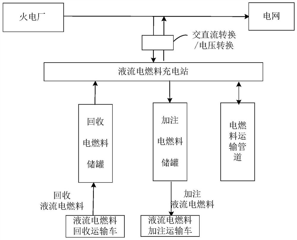
System and method for arranging redox flow electric fuel charging station in thermal power plant

A liquid flow electricity and thermal power plant technology, applied in the field of charging stations, can solve the problems of insufficient flexibility in peak regulation and difficulty in charging new energy vehicles, and achieve the effects of convenient battery logistics and transportation, fast charging process, and saving land resources

Pending Publication Date: 2021-07-16
HEPU ENERGY ENVIRONMENTAL TECHNOLOGY CO LTD
View PDF0 Cites 0 Cited by
  • Summary
  • Abstract
  • Description
  • Claims
  • Application Information

AI Technical Summary

Problems solved by technology

[0009] Aiming at the deficiencies of the prior art, the present invention aims to provide a system and method for setting a liquid flow electric fuel charging station in a thermal power plant, which can realize large-capacity, centralized, efficient and safe liquid flow by using cheap electricity in a thermal power plant For the application of electric fuel energy storage, thermal power plants can obtain peak-shaving subsidies, and charging stations can obtain the lowest charging cost price with negative electricity prices, so as to overcome the current lack of peak-shaving flexibility of thermal power plants and the difficulty of charging new energy vehicles The problem

Method used


Image

  • System and method for arranging redox flow electric fuel charging station in thermal power plant
  • System and method for arranging redox flow electric fuel charging station in thermal power plant
  • System and method for arranging redox flow electric fuel charging station in thermal power plant

Examples


Embodiment 1

[0039]This embodiment provides a system in which a hydroelectric fuel charging station is installed in a thermal power plant, which can use the charging and discharging of the hydroelectric fuel group in the hydroelectric fuel charging station to respond to power grid peak regulation, frequency modulation, black start, and interruptible storage. For any of the grid auxiliary services such as electric loads, the fully charged liquid flow electric fuel cell can be refilled to the car, and the liquid flow electric fuel cell that the user has exhausted can be recycled to the thermal power plant and injected back into the charging station for recharging.

[0040] Specifically, as figure 2 As shown, the system of this embodiment includes a high-voltage transformer 1, a high-voltage switch 2, a medium-voltage transformer 3, a medium-voltage switch 4, a factory power transformer 5, a factory transformer switch 6, and a charging station. The charging station includes a charging and dis...

Embodiment 2

[0049] Such as image 3 As shown, this embodiment provides a control method for a system using a liquid flow electric fuel charging station in a thermal power plant, specifically:

[0050] S10: When it is necessary for the thermal power plant to reduce the power generation, the grid power dispatching center 104 sends a scheduling command to the power plant centralized control system 102 of the thermal power plant. When the control cabinet 7 sends a charging command, the electric energy output by any one of the output bus bar of the generator of the thermal power plant, the bus bar of the booster station, and the bus bar of the plant power output is output to the charge and discharge control cabinet 7, and the charge and discharge control cabinet 7 After converting alternating current to direct current, charge the hydroelectric fuel cell of the hydroelectric fuel charging station;

[0051] S11: The centralized control system 102 of the power plant obtains the charging informat...

Embodiment 3

[0056] Such as Figure 4 As shown, this embodiment provides a method for configuring a system for setting a liquid-electric fuel charging station in a thermal power plant, including the following steps:

[0057] S20. According to the type of thermal power plant and the type of grid auxiliary services that can be carried out in cooperation with the local thermal power plant and the grid, determine whether the liquid flow electric fuel charging station is a one-way charging operation mode or a two-way charging and discharging operation mode;

[0058] S21. According to the power generation scale of the thermal power plant, the depth and load of the thermal power plant's participation in the peaking and frequency regulation of the grid auxiliary services, and the demand for the liquid flow electric fuel cell that needs to be guaranteed for external sales, determine the liquid flow electric fuel charging station The capacity of the flow electric fuel cell.

[0059] In this embodim...


PUM


Abstract

The invention provides a system and a method for arranging a redox flow electric fuel charging station in a thermal power plant. The system comprises a redox flow electric fuel cell charging station in the thermal power plant, the redox flow electric fuel cell charging station comprises a charging and discharging control cabinet, a redox flow electric fuel cell and a storage tank thereof, the charging and discharging control cabinet controls charging and discharging of the redox flow electric fuel cell, the thermal power plant is electrically connected with the charging and discharging control cabinet through the switch, and the power plant centralized control system controls and is connected with the charging and discharging control cabinet. The system has the beneficial effects that land resources can be effectively saved; the battery of the charging station participates in power grid frequency modulation auxiliary service; and the redox flow electric fuel cell is fast in charging process and convenient in battery logistics transportation.

Description

technical field [0001] The invention relates to the technical field of charging stations, in particular to a system and method for setting a liquid flow electric fuel charging station in a thermal power plant. Background technique [0002] Generally speaking, electric energy cannot be stored (the current battery energy storage cost is high and the energy storage capacity is limited), so the thermal power plant needs to generate as much electricity as the user needs, so as not to cause energy waste. But usually in the power system, the demand load of each thermal power plant is constantly changing. In order to maintain the balance of active power and keep the system frequency stable, the power generation department needs to change the power generation of the generator accordingly to adapt to the change of power load. This is called peak shaving. [0003] In China's three northern regions, the power market capacity is abundant, gas turbines, pumped storage and other peak-adju...

Claims


Application Information

Patent Timeline
Patent Type & Authority Applications(China)
IPC IPC(8): H02J3/32B60L53/54
CPCB60L53/54H02J3/32Y02T10/70Y02T10/7072Y02T90/12
Inventor 金红光崔华杨豫森陈辉
Owner HEPU ENERGY ENVIRONMENTAL TECHNOLOGY CO LTD
Learn More