Glass plate tempering device utilizing contact method
A glass plate and contact method technology, which is applied in glass tempering, glass manufacturing equipment, manufacturing tools, etc., can solve the problems of incomplete tempering, poor tempered glass products, and insufficient quenching of the glass clamping part, and achieve faster quenching effect
- Summary
- Abstract
- Description
- Claims
- Application Information
AI Technical Summary
Problems solved by technology
Method used
Image
Examples
Embodiment 1
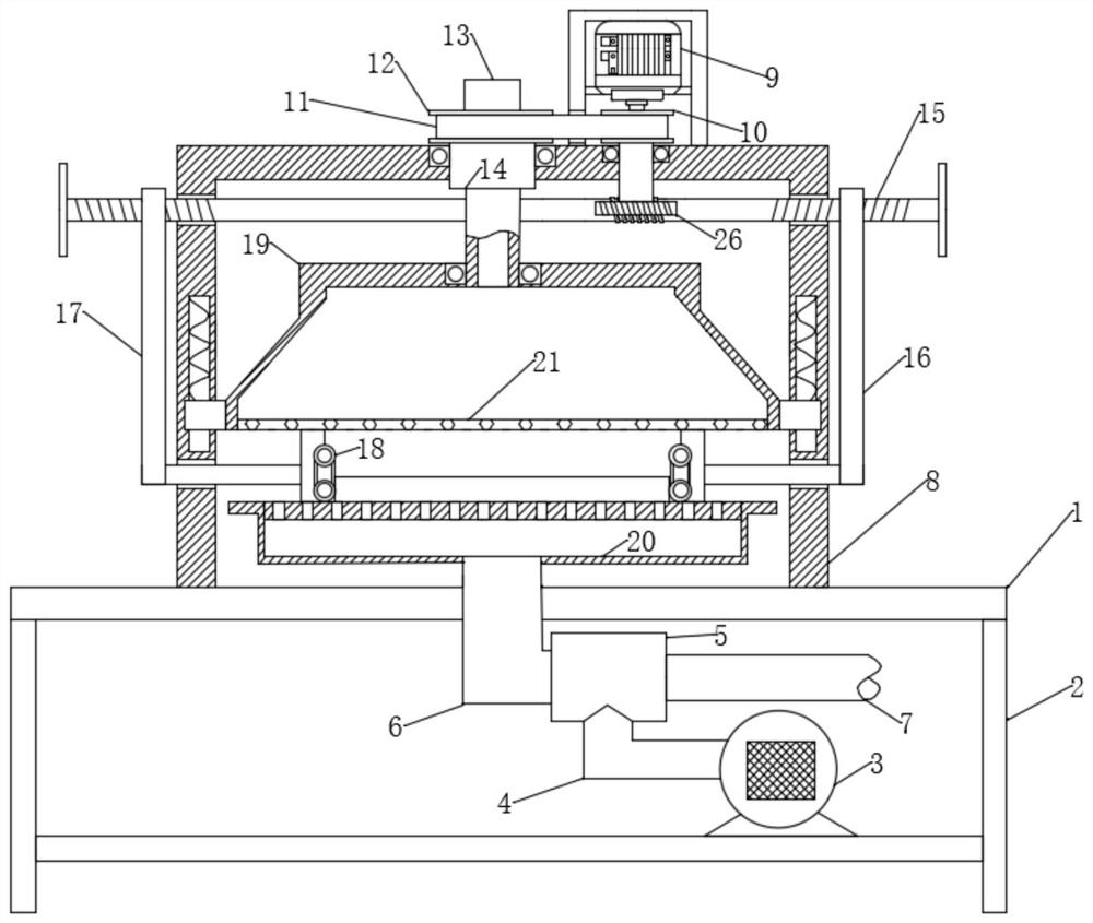
[0022] like figure 1 As shown, a glass plate tempering device using the contact method includes a base 1, a support plate 2 is provided on the lower side of the base 1, an air compressor 3 is provided at the lower end of the support plate 2, and a ventilation pipe 4 is provided at one end of the air compressor 3. The upper end of the ventilation pipe 4 is fixedly connected with a vortex chamber 5, the vortex chamber 5 is provided with a cold air pipe 6 at the middle end of the base 1, the other end of the vortex chamber 5 is provided with a hot air pipe 7, the middle end of the base 1 is fixedly connected with the cold air pipe 6, and the base 1 The upper end is provided with a housing 8, the housing 8 is provided with a workbench 20 near the end of the cold air pipe 6, the upper end of the housing 8 is rotatably connected with a movable nut 14, and the upper end of the movable nut 14 is coaxially fixedly connected with a second pulley 12, and the movable nut 14 A screw rod 13...
Embodiment 2
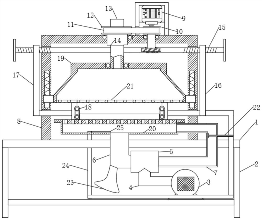
[0029] like figure 2As shown, the difference between this embodiment and Embodiment 1 is that the right fixed frame 16 is fixedly connected to the movable plate 24 away from the belt mechanism 18 ends, and the movable plate 24 is fixedly connected to the deflector 22 by the end of the hot air pipe 7. The flow plate 22 is slidably connected with the hot air pipe 7, and the hot air pipe 7 is provided with a left and right movable groove at the end of the flow deflector 22, and the flow deflector 22 is slidably connected in the movable groove, and the inner end of the flow deflector 22 is provided with an L-shaped The deflector hole, the deflector 22 is provided with a small baffle away from the end of the movable plate 24. By setting the L-shaped deflector hole, the deflector 22 is convenient for hot air to be discharged. By setting the small baffle, the deflector 22 is prevented from moving from the movable groove Inner prolapse.
[0030] The moving plate 24 is slidably conne...
PUM
 Abstract
Description
Claims
Application Information
 - R&D
- Intellectual Property
- Life Sciences
- Materials
- Tech Scout
- Unparalleled Data Quality
- Higher Quality Content
- 60% Fewer Hallucinations
Browse by: Latest US Patents, China's latest patents, Technical Efficacy Thesaurus, Application Domain, Technology Topic, Popular Technical Reports.
© 2025 PatSnap. All rights reserved.Legal|Privacy policy|Modern Slavery Act Transparency Statement|Sitemap|About US| Contact US: help@patsnap.com


