
On-line detection system and method of trace dissolved gas in organic oil

A technology of dissolved gas and detection system, applied in general control systems, control/regulation systems, measuring devices, etc., can solve the problems of small separation, long oil and gas balance time, large volume, etc., to achieve easy installation and maintenance, meet real-time requirements The effect of degassing, simplifying the number of channels

Inactive Publication Date: 2012-02-15
CENT SOUTH UNIV
View PDF0 Cites 19 Cited by
  • Summary
  • Abstract
  • Description
  • Claims
  • Application Information

AI Technical Summary

Problems solved by technology

In the past, there were problems in the online detection system of trace dissolved gas in oil, such as bulky system equipment, few types of dissolved gas in oil, long oil and gas equilibrium time, poor separation effect of dissolved gas, and insufficient detection accuracy of dissolved gas.
[0003] At present, the ordinary polymer degassing membrane oil-gas equilibrium time is long; the separation degree of each gas component in the traditional chromatographic system is small, resulting in the problem that O2 and CO gas are difficult to separate; for the detection of multi-component gases, the thermal conductivity method is mainly used. Sensors, hydrogen flame ionization sensors, semiconductor sensors, etc.
The main disadvantage of the thermal conductivity sensor is that the minimum detection limit is too large, and it needs flammable pure hydrogen as a carrier, which increases the risk of application; the hydrogen flame ionization sensor can detect too few types of gases; the semiconductor sensor has a long response time and is prone to smear

Method used


Image

  • On-line detection system and method of trace dissolved gas in organic oil
  • On-line detection system and method of trace dissolved gas in organic oil
  • On-line detection system and method of trace dissolved gas in organic oil

Examples


Embodiment 1

[0048] 1. System composition

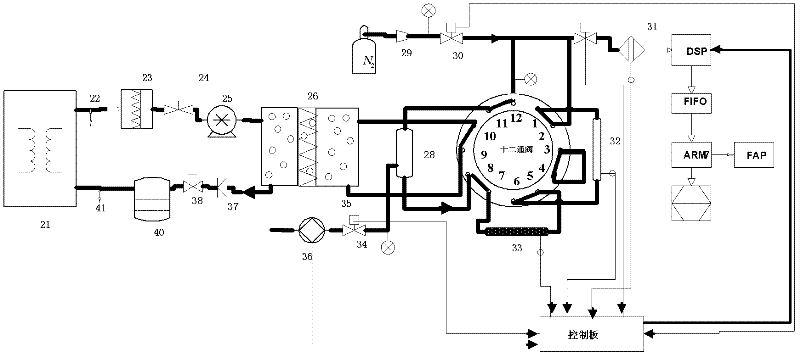
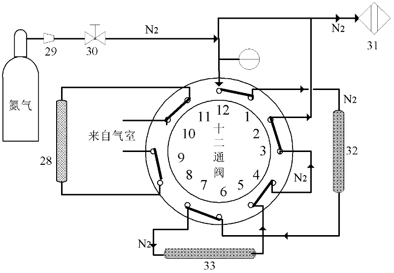
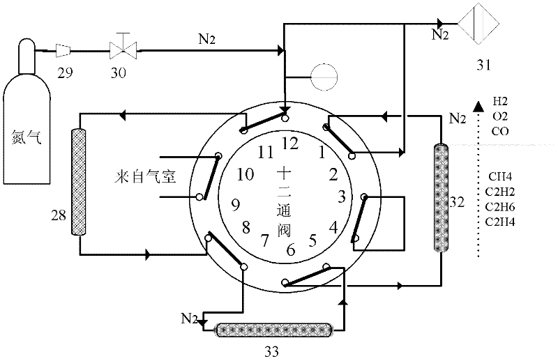
[0049] Refer to attached figure 1 , The system integration invention includes an oil-gas separation unit, a gas detection unit, and a control unit. The oil-gas separation unit includes organic oil pretreatment, oil-gas separation chamber part, and oil circulation buffer; the gas detection unit includes a carrier gas unit, a 12-way valve sampling module, a double-column mixed gas separation module, and a trace amount of combustible gas Sensor module; the control unit includes a motor control module, a temperature control module, a signal acquisition and data processing module, a status indication and fault processing module, and a data transmission module.

[0050] The oil-gas separation chamber part includes a micro-magnetic oil pump, a micro-air chamber, a Teflon PTFE fast degassing membrane, a check valve and a gas vacuum pump: the micro-magnetic oil pump pumps the pretreated organic oil at an appropriate speed under the control of the control...


PUM


Abstract

The invention discloses an on-line detection system and method of trace dissolved gas in organic oil, characterized in that: a polymer degassing film with short oil-gas balance time is used, thus the structure is simple, and degasification speed is fast; the trace dissolved gas in organic oil is separated through the dual column chromatography, thus the number of channels of traditional chromatograph is simplified; the unique twelve-way valve structure is used, and double chromatographic columns are arranged, thus the system works respectively alternately in states of reflux and sample injection, and the problem of difficult separation of O2 and CO gas existing in the traditional chromatographic system is effectively solved; a trace flammable gas detection sensor produced by using a solidoxide fuel cell technique can simultaneously detect 7 kinds of dissolved gases in organic oil with high detection accuracy and good separating degree of different component gases, and the number of gas sensor in the system is reduced. According to the invention, an oil-gas separation, a gas separation detection unit and a control unit are combined together, thus the volume of the system device isreduced, the stability of the system is increased, and the system is convenient for installation and maintenance.

Description

technical field [0001] The invention relates to an online detection system and method for trace amounts of dissolved gas in organic oil, in particular to an online monitoring of the dissolved gas content and change trend in oil during operation of ultra-high voltage three-phase integrated transformer oil or aeroengine lubricating oil A highly integrated online detection system and detection method for dissolved gas in organic oil and alarm. Background technique [0002] Many large-scale equipment, such as high-voltage and ultra-high-voltage transformers, aviation engine lubrication, etc., use organic oil for cooling and insulation. Due to overheating, electrical discharge, and their own hydrocarbon structure, these organic oils will produce combustible gases such as H 2 , CO, C 2 h 2 gas dissolved in oil. Moreover, the amount and composition of these gases directly reflect the health status of these large-scale equipment. For example, the current transformer fault diagno...

Claims


Application Information

Patent Timeline
Patent Type & Authority Applications(China)
IPC IPC(8): G01N30/02G01N30/14G05B19/048
Inventor 胡志坤丁家峰谢嘉祥王会海华长春
Owner CENT SOUTH UNIV
Learn More