
A kind of automatic control packaging machine and packaging method

A technology of packaging machine and packaging components, applied in the field of packaging, can solve the problems of single structure, inconvenient use, less design of discharging packaging, etc.

Active Publication Date: 2021-09-14
江苏金泰祥内外门业有限公司
View PDF9 Cites 0 Cited by
  • Summary
  • Abstract
  • Description
  • Claims
  • Application Information

AI Technical Summary

Problems solved by technology

The design and preparation of general packaging machines are based on different material transportation. The existing design is generally for direct packaging for receiving conveyor belt transportation, and there are also direct packaging for storage bins / device / boxes; existing The structure of the automatic control packaging machine is relatively simple, and the design of the discharge packaging for the storage bin / device / box is less, and it is often directly discharged and packaged from the discharge port. This method mainly relies on the support bracket and valve parts, and there are certain dangerous, not convenient for people to use

Method used


Image

  • A kind of automatic control packaging machine and packaging method
  • A kind of automatic control packaging machine and packaging method
  • A kind of automatic control packaging machine and packaging method

Examples


Embodiment 1

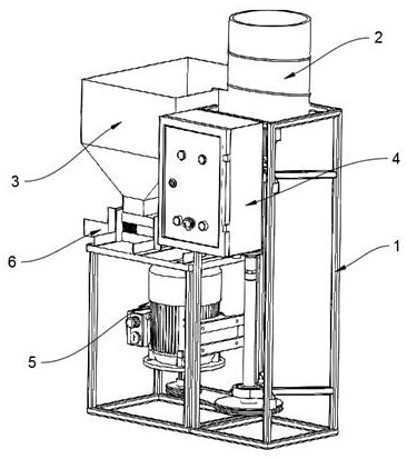
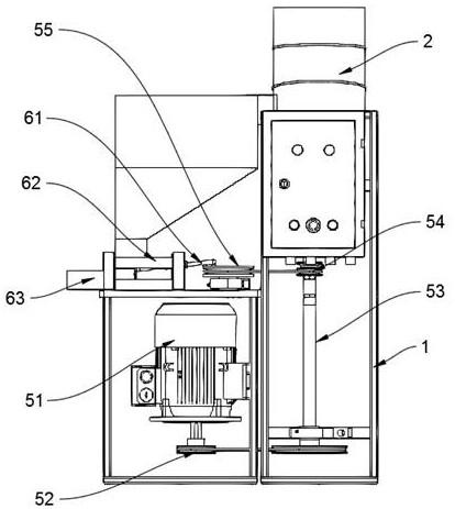
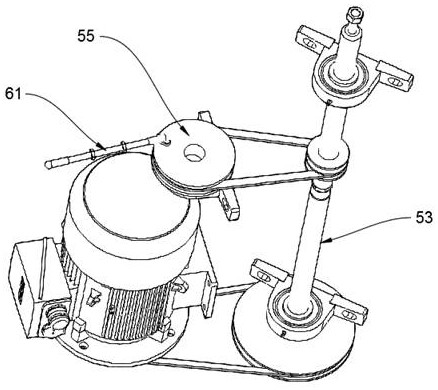
[0028] refer to figure 1 and figure 2 , a self-control packaging machine, including a bracket 1, a connecting pipe 2, a release funnel 3, an electric control box 4, a drive 5 and a packaging assembly 6, the outlet of the connecting pipe 2 and the feed of the release funnel 3 port connection, the packaging component 6 is arranged below the discharge port of the release funnel 3, after the material enters from the feed port of the connecting pipe 2, it is discharged from the discharge port of the connecting pipe 2 into the release funnel 3 , discharged from the discharge port of the release funnel 3, the packaging assembly 6 includes a carrier, a discharge rod and a discharge member 63, the material falls in the carrier, and the driving member 5 drives the discharge of the packaging assembly 6 The material rod pushes the material to be discharged from the discharge part 63, and enters the packaging bag or packaging box connected with the discharge part 63. The electric control...

Embodiment 2

[0032] refer to figure 1 and figure 2 , a self-control packaging machine, including a bracket 1, a connecting pipe 2, a release funnel 3, an electric control box 4, a drive 5 and a packaging assembly 6, the outlet of the connecting pipe 2 and the feed of the release funnel 3 port connection, the packaging component 6 is arranged below the discharge port of the release funnel 3, after the material enters from the feed port of the connecting pipe 2, it is discharged from the discharge port of the connecting pipe 2 into the release funnel 3 , discharged from the discharge port of the release funnel 3, the packaging assembly 6 includes a carrier, a discharge rod and a discharge member 63, the material falls in the carrier, and the driving member 5 drives the discharge of the packaging assembly 6 The material rod pushes the material to be discharged from the discharge part 63, and enters the packaging bag or packaging box connected with the discharge part 63. The electric control...

Embodiment 3

[0036] refer to figure 1 and figure 2 , a self-control packaging machine, including a bracket 1, a connecting pipe 2, a release funnel 3, an electric control box 4, a drive 5 and a packaging assembly 6, the outlet of the connecting pipe 2 and the feed of the release funnel 3 port connection, the packaging component 6 is arranged below the discharge port of the release funnel 3, after the material enters from the feed port of the connecting pipe 2, it is discharged from the discharge port of the connecting pipe 2 into the release funnel 3 , discharged from the discharge port of the release funnel 3, the packaging assembly 6 includes a carrier, a discharge rod and a discharge member 63, the material falls in the carrier, and the driving member 5 drives the discharge of the packaging assembly 6 The material rod pushes the material to be discharged from the discharge part 63, and enters the packaging bag or packaging box connected with the discharge part 63. The electric control...


PUM


Abstract

The invention relates to an automatic control packaging machine and a packaging method. The self-control packaging machine includes a bracket, a connecting pipe, a release funnel, an electric control box, a drive and a packaging assembly, the outlet of the connecting pipe is connected to the inlet of the release funnel, and the packaging assembly is set Below the discharge port of the release funnel, after the material enters from the feed port of the connecting pipe, it is discharged from the discharge port of the connection pipe into the discharge funnel, and discharged from the discharge port of the release funnel. The packaging The assembly includes a carrier, a discharge rod and a discharge member. The material falls into the carrier, and the driving member drives the discharge rod of the packaging assembly to push the material to discharge from the discharge part, and then enters and connects with the discharge part. In the packing bag or packing box, the electric control box is connected with the driving part, and the electric control box controls the opening and closing of the driving part.

Description

technical field [0001] The invention belongs to the technical field of packaging, and in particular relates to an automatic control packaging machine and a packaging method. Background technique [0002] Packaging machinery has a wide range of uses. At present, food, chemical, pharmaceutical, and light industries are all used in the market. The design and preparation of general packaging machines are based on different material transportation. The existing design is generally for direct packaging for receiving conveyor belt transportation, and there are also direct packaging for storage bins / device / boxes; existing The structure of the automatic control packaging machine is relatively simple, and the design of the discharge packaging for the storage bin / device / box is less, and it is often directly discharged and packaged from the discharge port. This method mainly relies on the support bracket and valve parts, and there are certain dangerous and inconvenient for people to us...

Claims


Application Information

Patent Timeline
Patent Type & Authority Patents(China)
IPC IPC(8): B65B1/04B65B1/00B65B37/00B65B39/00B65B59/00
CPCB65B1/00B65B1/04B65B37/00B65B39/00B65B59/00B65B59/001
Inventor 李苏州
Owner 江苏金泰祥内外门业有限公司
Learn More