
Special hob relief grinding device for numerical control lathe

A technology of CNC lathes and special devices, which is applied in the direction of grinding drive devices, grinding machine parts, grinding racks, etc., to achieve the effects of reducing the unbalanced load of the force, synchronizing the pitching movement, and conveniently balancing

Active Publication Date: 2021-07-16
HENAN UNIV OF SCI & TECH
View PDF9 Cites 0 Cited by
  • Summary
  • Abstract
  • Description
  • Claims
  • Application Information

AI Technical Summary

Problems solved by technology

[0004] The purpose of the present invention is to provide a hob relief grinding special device for CNC lathes, which can perform hob relief grinding on the existing CNC lathes of the enterprise, so as to solve the problem of purchasing CNC lathes in the prior art. Technical Problems in Hob Relief Grinding

Method used


Image

  • Special hob relief grinding device for numerical control lathe
  • Special hob relief grinding device for numerical control lathe
  • Special hob relief grinding device for numerical control lathe

Examples


Embodiment 1

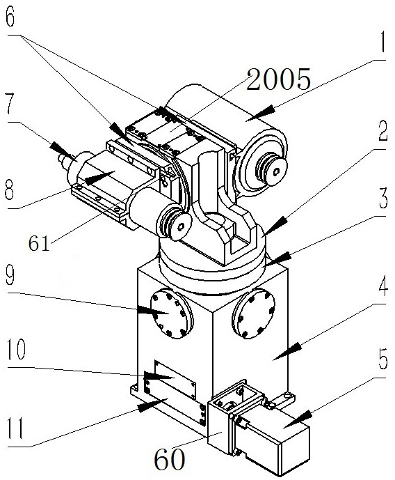
[0058] The special device 300 for hob relief grinding in this embodiment can be installed on the carriage 400 on the numerically controlled lathe. Cooperate with the knife and the workpiece to realize the relief grinding of the hob.

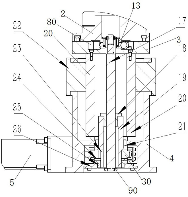
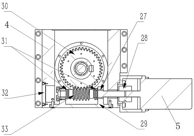
[0059] like Figure 1 to Figure 15 As shown, the hob shovel grinding special device 300 as a whole includes a base 4, a lifting platform 3, a rotary support 2 and a grinding head 7. The grinding head 7 is used to install the grinding wheel, and the lifting platform 3 is driven by a screw nut mechanism and can be assembled up and down. On the base 4, the rotary bracket 2 is rotatably mounted on the lifting platform 3 around the vertical axis, and can be lifted and lowered synchronously with the lifting platform 3. The grinding head 7 can be pitched and swung around the horizontal axis and mounted on the rotary bracket 2 to adjust the grinding. angle, the grinding head 7 rotates to perform corresponding relief grinding on the hob.

[0060] The sp...

specific Embodiment 2

[0090] It differs from Embodiment 1 mainly in that: in Embodiment 1, the lifting servo motor is located beside the base. In this embodiment, the lifting servo motor can be arranged under the base. At this time, the lifting worm gear mechanism can be omitted, and the lifting nut can be driven to rotate through the reduction gear mechanism to drive the lifting screw to move up and down.

specific Embodiment 3

[0092] It differs from Embodiment 1 mainly in that: in Embodiment 1, both the rotation adjustment mechanism and the pitch swing adjustment mechanism are worm and gear mechanisms, and a manual operating lever is configured to realize manual operation. In this embodiment, the manual operation lever is omitted, and all servo motors are configured.


PUM


Abstract

The invention relates to a special hob relief grinding device for a numerical control lathe. The special hob relief grinding device for the numerical control lathe comprises a base, a lifting table, a rotary support and a grinding head mounting seat, wherein the base is used for being mounted on a corresponding carriage of the numerical control lathe; the lifting table is mounted on the base through a lifting driving mechanism in the vertical direction in a lifting mode; the rotary support is assembled on the lifting table around a vertical rotary axis in a rotary mode, and the rotary support is driven by a rotary driving mechanism to achieve rotary adjustment; and the grinding head mounting seat can be mounted on the rotary support in a pitching swinging mode around a pitching swinging axis, a grinding head is rotationally assembled on the grinding head mounting seat, the grinding head is driven by a grinding wheel motor to rotate, the grinding head is used for mounting a grinding wheel, and the grinding head mounting seat is driven by a pitching swinging adjusting mechanism to realize pitching swinging adjustment. By means of the special hob relief grinding device, hob relief grinding can be conducted on the numerical control lathe, a numerical control relief grinding machine tool does not need to be specially purchased, and cost is low.

Description

technical field [0001] The invention relates to a hob cutter relief grinding special device for a numerically controlled lathe. Background technique [0002] Gear hobs are used as machining tools for hobbing gears. A typical gear hob is made of high-speed steel, and the side and flank of the hob are processed on a CNC hob grinder with a grinding wheel relief. [0003] At present, the relief grinding of the gear hob is mostly processed on a special CNC hob relief grinding machine, such as the CNC hob relief grinding machine disclosed in the Chinese utility model patent with the authorized announcement number CN201040329Y, which is based on the traditional The shovel back lathe is upgraded from the numerical control, and its core is the shovel moving box to drive the cam assembly, and the shovel grinding is completed by using the principle of leverage. Another example is the CNC relief grinding machine tool of the toroidal worm gear hob disclosed in the Chinese utility model...

Claims


Application Information

Patent Timeline
Patent Type & Authority Applications(China)
IPC IPC(8): B24B3/00B24B41/02B24B41/04B24B47/12B24B47/22
CPCB24B3/00B24B41/02B24B41/04B24B47/12B24B47/22
Inventor 李聚波孙维浩王松林闫晨宵王斌
Owner HENAN UNIV OF SCI & TECH
Learn More