Environment-friendly dust removal system using venturi tube
A dust removal system, using Wen's technology, applied in the field of venturi, can solve the problems of reducing the utilization rate of equipment, consuming a lot of time and manpower, and being difficult to disassemble, etc., to avoid gas leakage and ensure the airtight effect.
- Summary
- Abstract
- Description
- Claims
- Application Information
AI Technical Summary
Problems solved by technology
Method used
Image
Examples
Embodiment 1
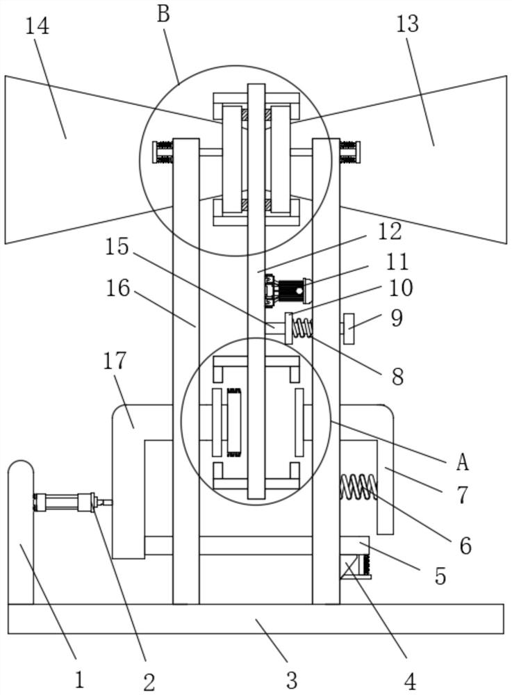
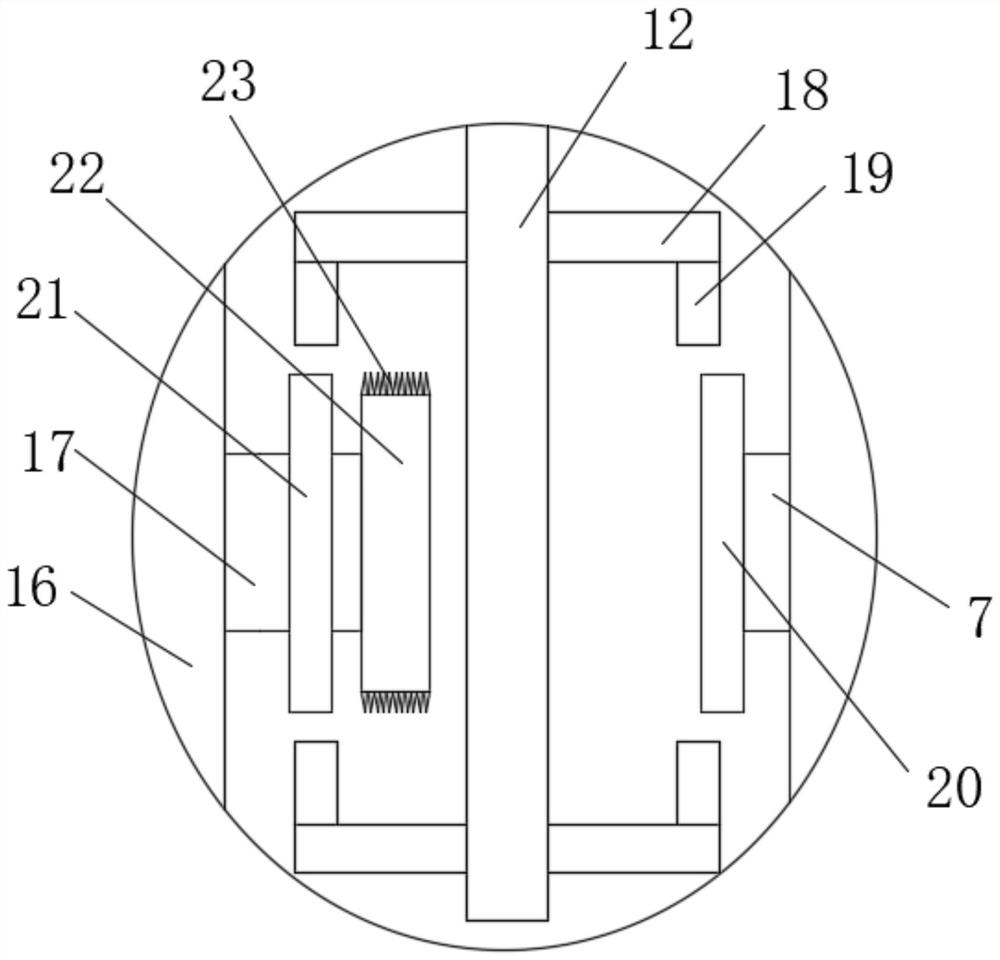
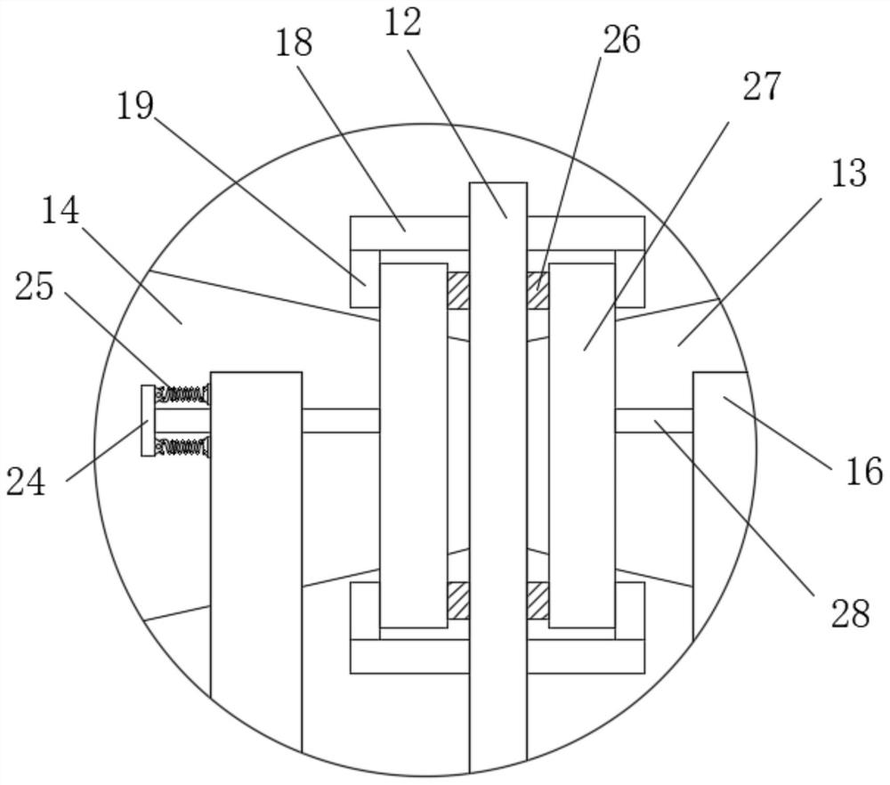
[0033] refer to Figure 1-8, an environment-friendly dust removal system using a venturi tube, comprising a bottom plate 3, two symmetrically arranged fixed plates 16 are fixedly connected to the top of the bottom plate 3, and the tops of one side of the two fixed plates 16 are respectively fixedly connected with a diffusion pipe 13 and a contraction The pipe 14 and the top of the side of the two fixed plates 16 close to each other are provided with a sealing assembly for sealing the connection between the diffuser tube 13 and the shrink tube 14, and one side of the fixed plate 16 is fixedly connected with a servo motor 11, the servo motor The output shaft of 11 is fixedly connected with a partition 12, and the upper and lower sides of the side where the partition 12 is far away from each other are symmetrically fixedly connected with two connecting plates 18, and the two adjacent connecting plates 18 located on the same side of the partition 12 are connected to each other. Th...
Embodiment 2
[0035] Further improvement on the basis of Embodiment 1: the sealing assembly includes a second sliding rod 28 that slides through the inside of the fixed plate 16, and the end of the second sliding rod 28 away from the partition 12 is fixedly connected with the second limiting plate 24, the second Two first extension springs 25 that are symmetrically arranged are fixedly connected between the two limiting plates 24 and the fixed plate 16, and a sealing plate 27 is fixedly connected to the end of the second sliding rod 28 near the dividing plate 12, and the two sealing plates 27 are respectively sleeved. Located on the diffuser tube 13 and the shrink tube 14, the limit assembly includes a clamping rod 15 that slides through the inside of the fixed plate 16, and two clamping slots 29 are opened on one side of the partition 12, and the clamping slots 29 engage with the clamping rod 15 One end of the clamp rod 15 away from the partition plate 12 is fixedly connected with a pull pl...
Embodiment 3
[0037] Further improvement on the basis of Embodiment 1: the bottom of the second L-shaped plate 17 away from the electric push rod 2 is fixedly connected with the first sliding rod 5, and the first sliding rod 5 runs through the two fixed plates 16, away from the side plate A fixed plate 16 of 1 is fixedly connected with a triangular block 4 on the side away from the partition 12, the inside of the first sliding rod 5 slides through and is connected with a bump 32, and the bottom of the bump 32 is fixedly connected with a The slant plate 34, the same second tension spring 33 is fixedly connected between the top of the slant plate 34 and the bottom of the first sliding rod 5, the inner wall of the sealing plate 27 is fixedly connected with the second sealing ring 31, and the sealing plate 27 is close to the partition One side of 12 is fixedly connected with the first sealing ring 26, the side of the convex plate 19 close to the sealing plate 27 is arc-shaped, and the side of th...
PUM
 Abstract
Description
Claims
Application Information
 - Generate Ideas
- Intellectual Property
- Life Sciences
- Materials
- Tech Scout
- Unparalleled Data Quality
- Higher Quality Content
- 60% Fewer Hallucinations
Browse by: Latest US Patents, China's latest patents, Technical Efficacy Thesaurus, Application Domain, Technology Topic, Popular Technical Reports.
© 2025 PatSnap. All rights reserved.Legal|Privacy policy|Modern Slavery Act Transparency Statement|Sitemap|About US| Contact US: help@patsnap.com


