
Control system and control method of BMS power switch

A technology for control systems and power switches, applied in electronic switches, electrical components, pulse technology, etc., can solve problems such as low reliability, huge bouncing noise in digital circuit systems, and huge working stress, and achieve simple and concise control logic and avoidance. Ground bounce noise, reduced complexity effects

Active Publication Date: 2021-07-13
ALPHA ESS CO LTD
View PDF7 Cites 0 Cited by
  • Summary
  • Abstract
  • Description
  • Claims
  • Application Information

AI Technical Summary

Problems solved by technology

[0006]③ The above two points will bring huge working stress to the MOSFET power switch on the main circuit and shorten the life of the entire BMS control system
[0007]④When the MOSFET power switch on the main circuit works, it brings huge ground bounce noise to the digital circuit system, introduces bounce noise to the signal ground of the control system, and reduces the BMS Reliability of control system signal ground system
[0008]⑤ Using high-power MOSFET, high cost, high overhead, poor economy
[0009]In order to solve the above defects, the industry usually adopts special ASIC (application specific integrated circuit) to design and realize the function of similar small stress power switch, but its cost is high, the economy is poor, and the control Complex logic and low reliability

Method used


Image

  • Control system and control method of BMS power switch
  • Control system and control method of BMS power switch
  • Control system and control method of BMS power switch

Examples


Embodiment Construction

[0031] The technical solutions of the present invention will be clearly and completely described below with reference to the accompanying drawings. Obviously, the described embodiments are a part of the embodiments of the present invention, but not all of the embodiments. Based on the embodiments of the present invention, all other embodiments obtained by those of ordinary skill in the art without creative efforts shall fall within the protection scope of the present invention.

[0032] In the description of the present invention, it should be noted that the terms "center", "upper", "lower", "left", "right", "vertical", "horizontal", "inner", "outer", etc. The indicated orientation or positional relationship is based on the orientation or positional relationship shown in the accompanying drawings, which is only for the convenience of describing the present invention and simplifying the description, rather than indicating or implying that the indicated device or element must hav...


PUM


Abstract

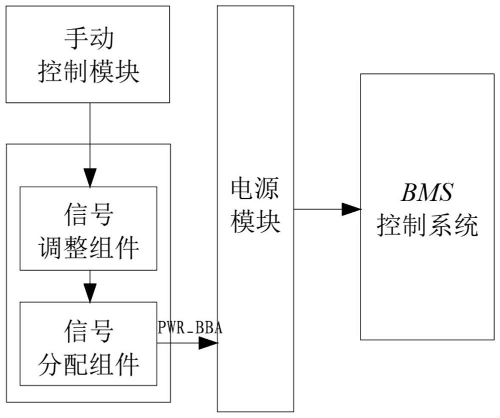
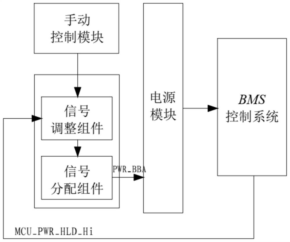
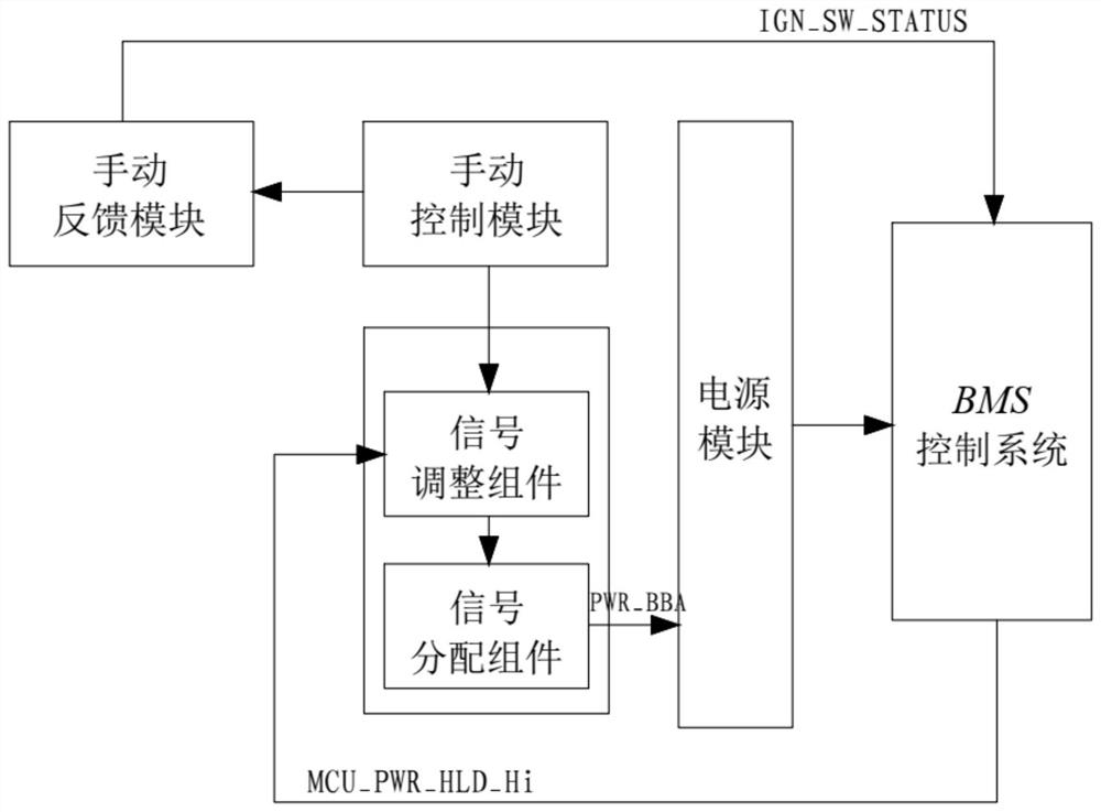
The invention relates to a control system and a control method of a BMS power switch, the control system comprises a switch module and a manual control module, the switch module comprises a signal distribution assembly and a signal adjustment assembly, and the signal distribution assembly receives an adjustment signal of the signal adjustment assembly; the signal distribution assembly distributes the signals and transmits the signals to the power supply module. Setting a first judgment threshold value and a second judgment threshold value in the power supply module; the initial output signal of the signal distribution assembly is larger than a first judgment threshold, and the signal adjustment assembly adjusts the output signal of the signal distribution assembly to be smaller than a second judgment threshold; the manual control module is used for closing the signal adjusting assembly; when the output signal is greater than a first judgment threshold value, the power supply module supplies power to the BMS control system; and when the output signal is smaller than the second judgment threshold value, the power supply module stops supplying power to the BMS control system. A minimum stress design is adopted, so that the defect of a high stress design is avoided; and the ground bounce noise caused by a main loop switch is avoided.

Description

technical field [0001] The invention relates to the technical field of battery control, in particular to a control system and a control method of a BMS power switch. Background technique [0002] At present, the battery packs used in the market need to be controlled by the BMS control system. The BMS control system is mainly to intelligently manage and maintain each battery unit, prevent the battery from overcharging and overdischarging, prolong the service life of the battery, and monitor the status of the battery. . [0003] The traditional BMS control system power switch control circuit is realized by using MOSFET on the main circuit for switching control. It belongs to a design method of high current and high voltage stress. The design is complicated and the reliability is low. [0004] ①The MOSFET power switch on the main circuit is stressed by the huge inrush current from the instantaneous charging of the capacitor. [0005] ②The MOSFET power switch on the main circu...

Claims


Application Information

Patent Timeline
IPC IPC(8): H03K17/687
CPCH03K17/687H02J7/0031
Inventor 陈义平司修利印志江袁宏亮林栋
Owner ALPHA ESS CO LTD
Learn More