Board cutting machine
A cutting machine, wood board technology, applied in sawing equipment, wood processing appliances, circular saws, etc., can solve problems such as inability to fix wood boards, operator injury, etc., and achieve the effect of reducing the probability of injury
- Summary
- Abstract
- Description
- Claims
- Application Information
AI Technical Summary
Problems solved by technology
Method used
Image
Examples
specific Embodiment approach 1
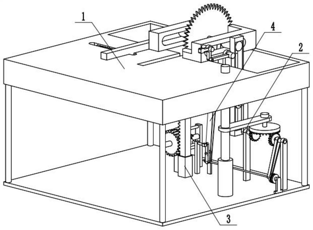
[0028] Combine below Figure 1-11 Describe this embodiment, a wood cutting machine, including a bracket assembly 1, a fixing assembly 2, a collection assembly 3, a transmission belt 4, the bracket assembly 1 is connected with the fixing assembly 2, the bracket assembly 1 is connected with the collection assembly 3, and the bracket assembly 1 is connected with the transmission belt 4, the fixed assembly 2 is connected with the collection assembly 3, and the collection assembly 3 is connected with the transmission belt 4.
specific Embodiment approach 2
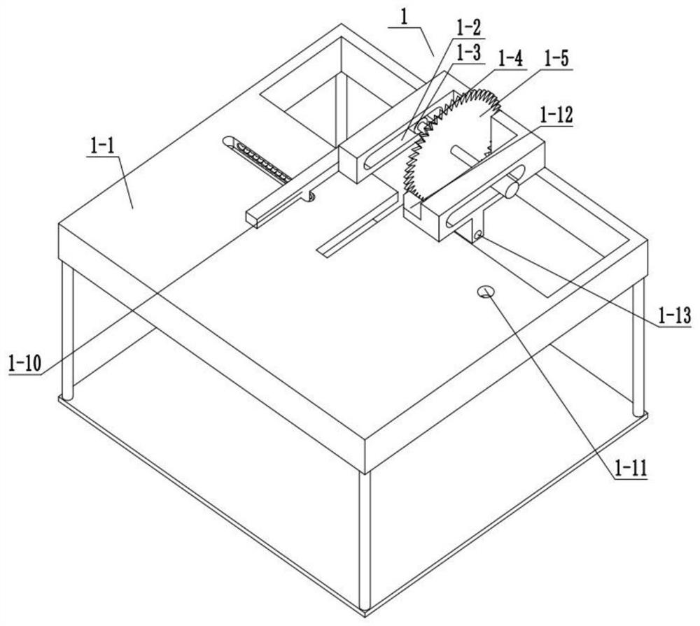
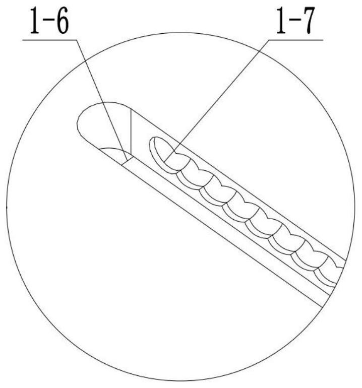
[0030] Combine below Figure 1-11 Describe this embodiment, this embodiment will further explain Embodiment 1, the bracket assembly 1 includes a fixed frame 1-1, a chute 1-2, a sliding bearing 1-3, a cutter shaft 1-4, and a blade 1 -5, chute two 1-6, groove 1-7, bump 1-8, spring one 1-9, fixed block one 1-10, through hole 1-11, angle plate 1-12, hinged column pass Holes 1-13, chute 1-2 are arranged on the fixed frame 1-1, chute 1-2 is slidingly connected with sliding bearing 1-3, and sliding bearing 1-3 rotates with cutter shaft 1-4 Connection, cutter shaft 1-4 is fixedly connected with blade 1-5, chute 2 1-6 is arranged on the fixed frame 1-1, groove 1-7 is arranged on chute 2 1-6, groove 1- 7 is fixedly connected with the bump 1-8, the bump 1-8 is slidingly connected with the fixed block 1-10, the spring 1-9 is in contact with the bump 1-8, and the fixed block 1-10 is connected with the fixed frame 1-10 1 sliding connection, the through hole 1-11 is arranged on the fixed f...
specific Embodiment approach 3
[0032] Combine below Figure 1-11Describe this embodiment, this embodiment will further explain the first embodiment, the fixed assembly 2 includes a sliding rod 2-1, a spring 2-2, a spring sleeve 2-3, a fixed rod 2-4, a transmission shaft 2-5, face gear 2-6, gear shaft one 2-7, gear shaft support one 2-8, rotating rod one 2-9, shaft 2-10, sliding bearing two 2-11, sliding block one 2-12 , cylindrical pin one 2-13, hinged column one 2-14, rotating rod two 2-15, sliding block two 2-16, hinged column bracket one 2-17, hinged column two 2-18, fixed block two 2-19 , the sliding rod one 2-1 is slidingly connected with the through hole 1-11, one end of the spring two 2-2 is in contact with the sliding rod one 2-1, the other end of the spring two 2-2 is in contact with the spring sleeve 2-3, and the spring sleeve 2-3 is fixedly connected with fixed frame 1-1, fixed rod 2-4 is fixedly connected with sliding rod one 2-1, fixed rod 2-4 is rotationally connected with transmission shaft ...
PUM
 Abstract
Description
Claims
Application Information
 - Generate Ideas
- Intellectual Property
- Life Sciences
- Materials
- Tech Scout
- Unparalleled Data Quality
- Higher Quality Content
- 60% Fewer Hallucinations
Browse by: Latest US Patents, China's latest patents, Technical Efficacy Thesaurus, Application Domain, Technology Topic, Popular Technical Reports.
© 2025 PatSnap. All rights reserved.Legal|Privacy policy|Modern Slavery Act Transparency Statement|Sitemap|About US| Contact US: help@patsnap.com


