Wireless electric energy transmission device

A wireless energy transmission, No. 1 technology, applied in the direction of circuit devices, battery circuit devices, devices with flexible leads, etc., can solve the problems of bottom damage, lack of protection, lack of mobile phone fixing, etc., to improve heat dissipation efficiency and avoid property loss , to avoid the effect of equipment evaluation

Inactive Publication Date: 2021-07-09
YANAN UNIV
View PDF0 Cites 1 Cited by
  • Summary
  • Abstract
  • Description
  • Claims
  • Application Information

AI Technical Summary

Problems solved by technology

Wireless charging technology is a special power supply method. It does not need a power line, relies on electromagnetic wave propagation, and then converts the energy of electromagnetic waves into electrical energy, and finally realizes wireless charging. And the bottom is easily damaged by water immersion, lack of protection, unstable connection, and lack of fixing to the mobile phone. A wireless power transmission device is proposed to meet the above requirements

Method used


Image

  • Wireless electric energy transmission device
  • Wireless electric energy transmission device
  • Wireless electric energy transmission device

Examples


Embodiment

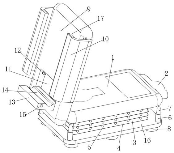
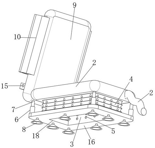
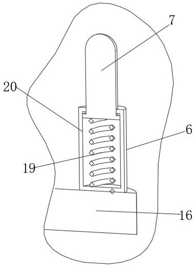
[0021] see Figure 1-5 , the present invention provides the following technical solutions: a wireless power transmission device, including a first charging module 1, one end of the first charging module 1 is installed with a charging line 2 engaged with a storage slot 4, the bottom of the first charging module 1 The heat dissipation module 3 is fixedly connected to the surface, and the surface of the heat dissipation module 3 is provided with a storage slot 4 for accommodating the charging line 2 around the surface. , the upper surface of the base plate 16 is provided with a connecting column 6 that is slidably connected with the limiting column 7, the upper end of the connecting column 6 is provided with a limiting column 7 that is elastically connected with the limiting spring 19, and the lower surface of the base plate 16 is fixedly connected with a suction cup 8, The center of the bottom plate 16 is provided with an air outlet groove 18, and the surface of the first chargi...


PUM


Abstract

The invention belongs to the technical field of wireless electric energy transmission, and particularly relates to a wireless electric energy transmission device which comprises a first charging module, one end of the first charging module is provided with a charging wire clamped with a storage groove, and the bottom surface of the first charging module is fixedly connected with a heat dissipation module. The periphery of the surface of the heat dissipation module is provided with a storage groove used for storing the charging wire, the surface of the storage groove is provided with heat dissipation holes in a penetrating mode, the bottom end of the heat dissipation module is fixedly connected with a bottom plate, by arranging a suction cup, the first charging module is stably connected with a table top, and the situation that the first charging module topples and falls off to affect use of equipment is avoided; by arranging the heat dissipation module and the bottom plate, the first charging module is higher than the table top, the heat dissipation efficiency is improved, and property damage and safety problems caused by the fact that a water cup topples over and water enters the interior are avoided; by setting a clamping block and a placement board, a mobile phone can be stably charged on the surface of a second charging module. the mobile phone is protected, and property loss caused by falling and damage of the mobile phone is avoided.

Description

technical field [0001] The invention belongs to the technical field of wireless power transmission, and in particular relates to a wireless power transmission device. Background technique [0002] With the continuous improvement of requirements for power supply quality, safety, reliability, convenience, immediacy, special occasions, and special geographical environments for electrical equipment, the contact power transmission method is increasingly unable to meet actual needs. Wireless chargers It is a device that uses the principle of electromagnetic induction for charging. Its principle is similar to that of a transformer. By placing a coil at the sending and receiving ends, the coil at the sending end sends out an electromagnetic signal to the outside under the action of electricity, and the coil at the receiving end receives the electromagnetic signal and converts it to the outside world. The electromagnetic signal is converted into electric current, so as to achieve the...

Claims


Application Information

Patent Timeline
Patent Type & Authority Applications(China)
IPC IPC(8): H02J50/00H02J50/40H02J7/00H01R13/72H05K5/02H05K7/20H02J50/10
CPCH01R13/72H02J7/0042H02J7/0044H05K5/0213H05K5/0234H05K7/20127H02J50/10H02J50/40H02J50/005
Inventor 朱小敏
Owner YANAN UNIV
Why Eureka
Try Eureka