
Four-channel micro valve based on dielectric wetting control

A dielectric wetting and four-channel technology, applied in the field of microfluidics, can solve the problems of single control and poor flexibility, and achieve the effects of improving service life, simple design, and preventing damage to components

Active Publication Date: 2021-07-09
GUANGZHOU UNIVERSITY
View PDF6 Cites 0 Cited by
  • Summary
  • Abstract
  • Description
  • Claims
  • Application Information

AI Technical Summary

Problems solved by technology

[0005] In microfluidic technology, the channels for liquid circulation are usually complex and diverse, and each channel is controlled independently of each other. The above-mentioned device is not suitable for controlling the connection and closing of multiple channels. Its single control has certain limitations and poor flexibility.

Method used


Image

  • Four-channel micro valve based on dielectric wetting control
  • Four-channel micro valve based on dielectric wetting control
  • Four-channel micro valve based on dielectric wetting control

Examples


Embodiment 1

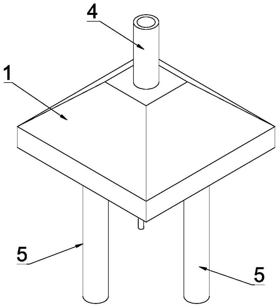
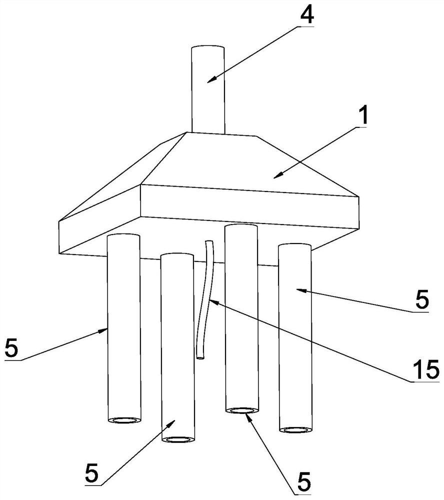
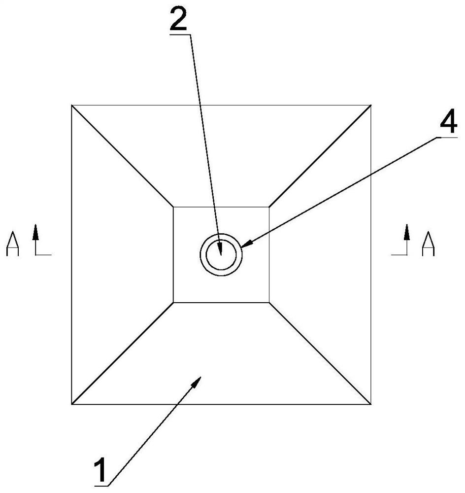
[0040] see Figure 1-Figure 5 , this embodiment discloses a four-channel microvalve based on dielectric wetting control, including a valve body 1, a liquid inlet 2 arranged at the upper end of the valve body 1, and four outlets arranged at the lower end of the valve body 1. The liquid port 3, the liquid inlet pipe 4 provided at the upper end of the liquid inlet port 2, and the liquid outlet pipe 5 arranged at the lower end of the liquid outlet port 3, wherein the valve body 1 is in the shape of a square prism, and the valve body 1 A valve cavity 6 is provided inside, the liquid inlet 2 and the four liquid outlets 3 communicate with the valve cavity 6 respectively, the liquid inlet pipeline 4 communicates with the liquid inlet 2, and the liquid outlet pipeline 5 It communicates with the liquid outlet 3.

[0041] see Figure 5-Figure 7 , the middle part of the valve chamber 6 is provided with a divider baffle 7 for guiding the liquid to flow around, there is a gap between the ...

Embodiment 2

[0062] see Figure 12 , the other structures in this embodiment are the same as in Embodiment 1, the difference is that the splitter baffle 7 is directly fixed on the mounting boss 13, and the elastic diaphragm 9 is rotatably arranged on the side of the splitter baffle 7. At the edge, the distance between two adjacent installation bosses 13 is the same as the width of the elastic diaphragm 9 . By arranging the above-mentioned structure, on the one hand, the airtightness between the elastic diaphragm 9 and the shunt partition 7 can be further improved, and the distance between two adjacent bosses is the same as the width of the elastic diaphragm 9, which can also ensure that the installation convex The tightness between the platform 13 and the diaphragm ensures the airtightness of the entire communication port 8 .


PUM


Abstract

The invention discloses a four-channel micro valve based on dielectric wetting control, which comprises a valve body, a liquid inlet formed in the upper end of the valve body and four liquid outlets formed in the lower end of the valve body, a valve cavity is formed in the valve body, the liquid inlet and the four liquid outlets respectively communicate with the valve cavity, a shunting partition plate is arranged in the middle of the valve cavity, gaps are formed between the periphery of the shunting partition plate and the inner wall of the valve body, the gaps in the periphery respectively form four communicating ports, the four liquid outlets correspond to the four communicating ports in position in a one-to-one mode, a micro valve control mechanism used for controlling the communicating ports to be opened and closed is arranged at the bottom of the valve cavity and comprises elastic membranes and dielectric wetting driving mechanisms, the elastic membranes are rotationally arranged at the communicating ports, and the dielectric wetting driving mechanisms are used for driving the elastic membranes to open and close the communicating ports. The four-channel micro valve can simultaneously control the communication and closing of four channels, and has the characteristics of wide control range, high adaptability, high flexibility and the like.

Description

technical field [0001] The invention relates to the technical field of microfluidics, in particular to a four-channel microvalve based on dielectric wetting control. Background technique [0002] Digital microfluidics (DMF, the abbreviation of digital microfluidics in English) has become a powerful liquid processing technology. Through the independent manipulation of micro-droplets, the reaction, analysis and detection of samples can be realized, and it is widely used in the field of biochemistry. Microvalve is an indispensable and important part of microfluidics. It is the "brain" of microfluidic control chips and is used to control the opening or closing of microfluidic channels. It has a wide range of potential applications in many fields such as electronics industry, national security, DNA sequencing, protein analysis, single cell analysis, drug screening, drug detection, food safety, and environmental monitoring. Microvalve is one of the main components of microfluidic...

Claims


Application Information

Patent Timeline
Patent Type & Authority Applications(China)
IPC IPC(8): F16K11/22F16K27/02F16K31/02
CPCF16K11/22F16K27/0263F16K31/02F16K99/0005F16K99/0028F16K99/0042
Inventor 江帆江志超祝韬陈美蓉温锦锋
Owner GUANGZHOU UNIVERSITY
Learn More