
High-strength tubular pile foundation pit support structure for geotechnical engineering

A geotechnical engineering and foundation pit support technology, which is applied in foundation structure engineering, sheet pile walls, excavation, etc., can solve problems such as small gripping force, weak shear resistance, and weak pull-out resistance, and achieve improved stability Performance and reliability, increased shear resistance, and improved installation strength

Pending Publication Date: 2021-07-09
LANZHOU UNIVERSITY
View PDF7 Cites 0 Cited by
  • Summary
  • Abstract
  • Description
  • Claims
  • Application Information

AI Technical Summary

Problems solved by technology

[0003] When the edge of the foundation pit is close to the red line area of ​​the building construction and cannot be sloped, pipe piles are usually used for foundation pit support. The traditional pipe piles are PHC pipe piles, and the bottom of the pile body is relatively smooth, which is driven into the soil. The holding force with the soil is small, and the pull-out resistance is weak, so that the PHC pipe pile is easy to be pulled out by the whole root when a landslide occurs. The capacity is weak, and when the side soil pressure is large, there may be fractures. On the other hand, because the PHC pipe piles are relatively smooth for the convenience of construction, it is inconvenient to connect each PHC pipe pile into a whole, so that the pipe pile supports The integrity of the protection becomes poor, and the installation of geotextiles or protective nets is not convenient, which is not conducive to on-site construction and maintenance, and needs to be improved

Method used


Image

  • High-strength tubular pile foundation pit support structure for geotechnical engineering
  • High-strength tubular pile foundation pit support structure for geotechnical engineering
  • High-strength tubular pile foundation pit support structure for geotechnical engineering

Examples


Embodiment Construction

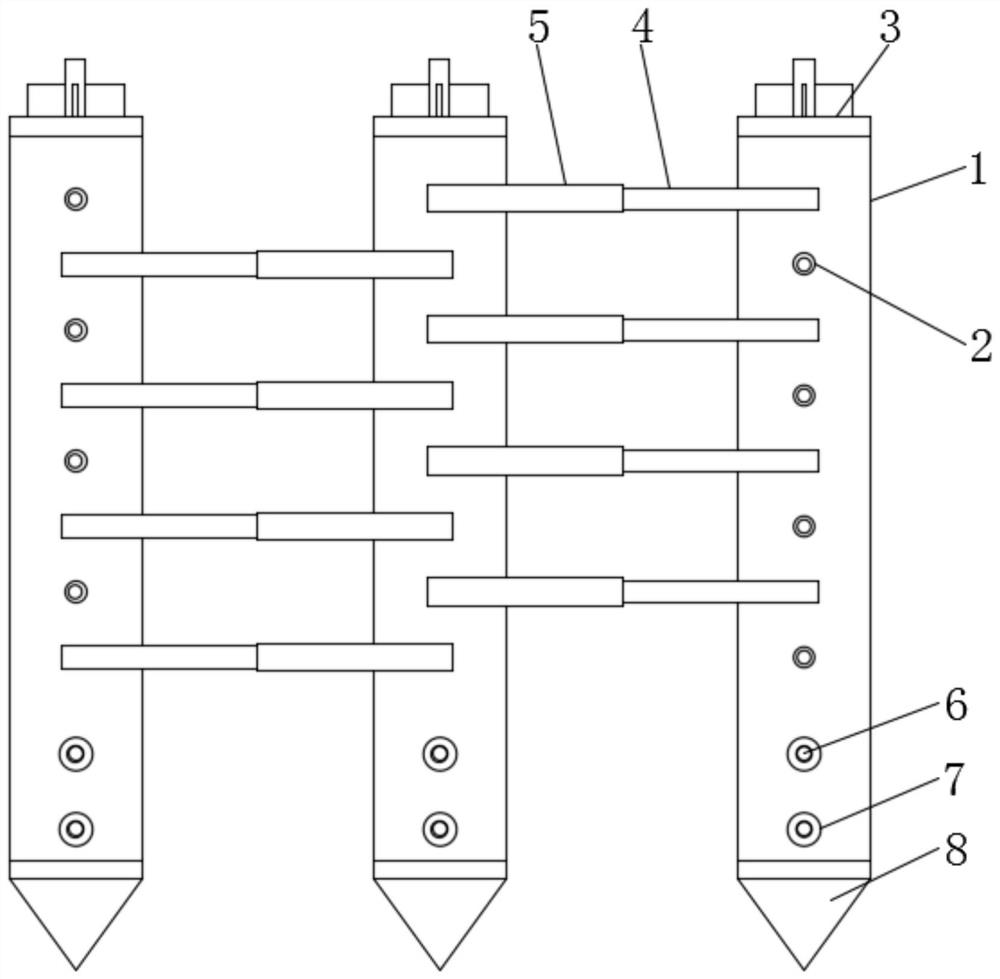
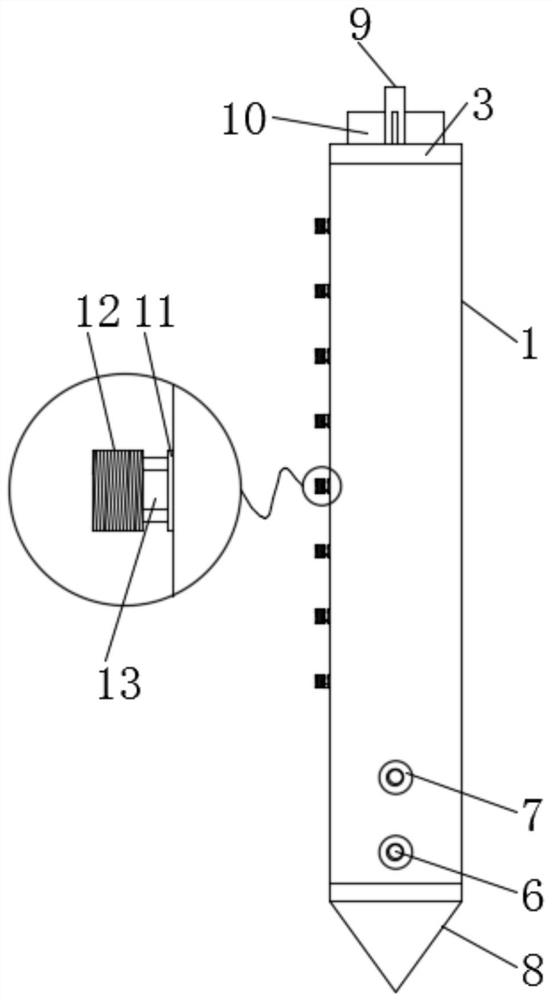
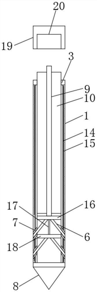
[0035] In order to further illustrate the various embodiments, the present invention provides accompanying drawings, which are part of the disclosure of the present invention, and are mainly used to illustrate the embodiments, and can be used in conjunction with the relevant descriptions in the specification to explain the operating principles of the embodiments, for reference Those of ordinary skill in the art should be able to understand other possible implementations and advantages of the present invention. The components in the figures are not drawn to scale, and similar component symbols are generally used to represent similar components.

[0036] According to an embodiment of the present invention, a high-strength pipe pile foundation pit support structure for geotechnical engineering is provided.

[0037] Now in conjunction with accompanying drawing and specific embodiment the present invention is further described, as Figure 1-8As shown, a high-strength tubular pile f...


PUM

PropertyMeasurementUnit
Lengthaaaaaaaaaa

Abstract

The invention discloses a high-strength tubular pile foundation pit support structure for geotechnical engineering. The high-strength tubular pile foundation pit support structure comprises a pile body and a top cap. The high-strength tubular pile foundation pit support structure has the beneficial effects that an upper sliding plate, a lower sliding plate, a soil piercing rod and a steel column are adopted, the top surface of the top cap covers the top surface of a top steel ring in the foundation pit support process, the top surface of an avoidance groove is abutted with the top surface of the steel column at the moment, the top cap is pressed downwards by adopting a static pile press machine, the pile body is pushed into a soil layer by the top cap, after the pile body is driven to the set depth, the direction of the top cap is adjusted, the top surface of the avoidance groove is abutted with the top surface of the steel column, the top cap is continuously pressed downwards by adopting the static pile press machine, and the steel column is pushed to move downwards by the top cap, so that the upper sliding plate and the lower sliding plate are pushed to move downwards, then the soil piercing rod is pushed to obliquely move downwards to pierce into soil and extend into the soil like plant rooting, and the pulling resistance of the bottom of the pile body and the soil is increased, the mounting stability of the pile body is increased, the mounting strength is increased, and the device is stable and reliable.

Description

technical field [0001] The invention relates to the technical field of foundation pit support, in particular to a high-strength pipe pile foundation pit support structure for geotechnical engineering. Background technique [0002] The foundation pit is an earth pit excavated at the foundation design position according to the base elevation and foundation plane size. If the excavation is not deep, the side slope can be used to stabilize the soil slope. The slope size is determined according to the relevant construction engineering regulations. If the excavation is deep and there are buildings nearby, the method of foundation pit wall support and sprayed concrete wall protection method can be used. Large-scale foundation pits even use methods such as underground diaphragm walls and column-type bored pile interlocking to protect the outer soil layer from collapsing. There is no influence on nearby buildings. The well point method can be used to reduce the groundwater level. Th...

Claims


Application Information

Patent Timeline
IPC IPC(8): E02D17/04E02D5/30E02D7/20
CPCE02D17/04E02D5/30E02D7/20
Inventor 马亚维郭桂红王戬陈洋帆
Owner LANZHOU UNIVERSITY
Learn More