
Spinoscope and percutaneous pedicle screw composite system

A pedicle screw and composite system technology, which is applied in the field of spinal mirror and percutaneous pedicle screw composite system, can solve the problems of poor screw fastening, affecting the operation effect, and single screw, so as to improve the fixation effect, Avoid excessive concentration of stress and the effect of avoiding stress concentration

Pending Publication Date: 2022-06-24
LUOYANG ORTHOPEDIC TRAUMATOLOGICAL HOSPITAL
View PDF0 Cites 0 Cited by
  • Summary
  • Abstract
  • Description
  • Claims
  • Application Information

AI Technical Summary

Problems solved by technology

[0003] Most of the existing pedicle screws are solid or have holes. Most of the holes are used for injecting bone cement or drugs. The essence is still a screw. In actual use, the force of spinal fixation and pulling Both directly act on the screw, and the screw acts on the screw hole of the pedicle. On the one hand, the screw is under a single static pull for a long time, and the stress is relatively concentrated, which may cause the screw to deform and loosen. , the tightening degree of the screw is basically determined by the tightening degree of the screw. To a certain extent, the tighter the screw is, the better the fixation effect is. However, for patients with osteoporosis, it is difficult for medical staff to control The tightening force will lead to poor screw tightening, which will affect the surgical effect

Method used


Image

  • Spinoscope and percutaneous pedicle screw composite system
  • Spinoscope and percutaneous pedicle screw composite system
  • Spinoscope and percutaneous pedicle screw composite system

Examples


Embodiment Construction

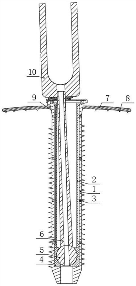
[0033] In this example, the combined system of the spinal mirror and percutaneous pedicle screw, please refer to Figure 1-2, including a screw sleeve 1, a connecting rod 6 and a nail base 10, the connecting rod 6 is worn in the screw sleeve 1, and the first end of the connecting rod 6 is movably connected to the inner wall of the first end of the screw sleeve 1 , the first end of the connecting rod 6 is fixedly connected with a ball head 5, the first end of the screw sleeve 1 is fixedly connected with a ball seat 4, and the ball head 5 is rotatably installed in the ball seat 4, A through hole is opened in the connecting rod 6 along its axis, and a through hole is also opened in the ball head 5. The through hole in the connecting rod 6 is coaxial and communicated with the through hole in the ball head 5, The cross-sectional shape of the through hole is hexagonal. The second end of the connecting rod 6 passes through the second end of the screw sleeve 1 and is fixedly connecte...


PUM


Abstract

The spinal mirror and percutaneous pedicle screw composite system comprises a screw sleeve, a connecting rod and a screw seat, the connecting rod penetrates into the screw sleeve, the first end of the connecting rod is movably connected with the inner wall of the first end of the screw sleeve, and the second end of the connecting rod is movably connected with the inner wall of the second end of the screw sleeve. The second end of the connecting rod penetrates out of the second end of the screw sleeve and is fixedly connected with the first end of the screw base. According to the pedicle screw, the screw sleeve and the connecting rod are arranged and matched with the ball seat, the ball head, the conical surface cushion seat and the spherical surface gasket, so that the connecting rod can be finely adjusted by any angle in the circumferential direction, the accuracy of the screw angle is indirectly improved, and the telescopic anti-loosening mechanism is arranged, and the driving block controls the jacking block to stretch out and jack the hole wall of a pedicle screw hole; on one hand, the overall pulling resistance and tension resistance of the screw are improved, and on the other hand, the screw sleeve can be effectively prevented from loosening, so that the fixing degree does not completely depend on the tightening degree of the screw.

Description

technical field [0001] The present invention relates to the technical field of spinal surgery. Specifically, it is a composite system of spinal mirror and percutaneous pedicle screw. Background technique [0002] The pedicle screw technique is a surgical method used to treat the spine. The pedicle is one of the components of the pedicle. Simply put, the pedicle screw technique is to place a screw on the pedicle, and then put multiple The screws are connected to each other to fix the spine to a certain extent, so as to achieve the purpose of treating the spine. [0003] Most of the existing pedicle screw is a solid screw or a screw with a hole. The hole is mostly used for injecting bone cement or drugs, etc., and its essence is still a screw. Both directly act on the screw, and the screw acts on the screw hole of the pedicle. On the one hand, the screw is in a single static pull for a long time, and the stress is relatively concentrated, which may lead to deformation and lo...

Claims


Application Information

Patent Timeline
Patent Type & Authority Applications(China)
IPC IPC(8): A61B17/86A61B17/70A61B1/317
CPCA61B17/8625A61B17/8615A61B17/7074A61B1/317
Inventor 王勇飞
Owner LUOYANG ORTHOPEDIC TRAUMATOLOGICAL HOSPITAL
Learn More