
Steam turbine unit mounting technology

An installation process and technology for steam turbine units, applied in the field of steam turbines, can solve the problems of frequent maintenance and difficult control of installation process quality, and achieve the effects of strong continuity, avoiding the risk of midway downtime and reducing rework.

Active Publication Date: 2021-07-09
四川华川基业建设集团有限公司
View PDF14 Cites 1 Cited by
  • Summary
  • Abstract
  • Description
  • Claims
  • Application Information

AI Technical Summary

Problems solved by technology

[0009] In order to solve the problem of the difficulty in quality control of the steam turbine unit installation process in the prior art, resulting in frequent repairs and maintenance, a steam turbine unit installation process is provided

Method used


Image

  • Steam turbine unit mounting technology

Examples


Embodiment 1

[0060] A steam turbine installation process, comprising the steps of:

[0061] S1. Process preparation: check that the strength and precision of the equipment meet the installation requirements of the unit, and the foundation surface is required to be flat and free of defects such as cracks, holes, honeycombs, pitted surfaces, and exposed ribs;

[0062] S2. Arrangement of parallel irons: Lay out the line according to the layout of the parallel irons, draw the position of the parallel irons, polish the position of the parallel irons, chisel the concrete surface where the parallel irons are installed to make the four corners of the parallel irons flat, and use the joint surface between the parallel irons and the concrete The coloring method checks to make the contact uniform, and the installation of pad iron requires uniform force everywhere;

[0063] The use of inclined pads must be paired, and the inclined plane must be corrected to ensure that the contact of the inclined plan...

Embodiment 2

[0087] On the basis of Example 1, when the generator bearing seat is installed, clean the insulating backing plate, and there must be no oil, sundries and other factors that affect the insulation. The insulation level is measured with a 1000V megohmmeter, and the resistance value must not be less than 1MΩ. Use a level to measure the elevation of the midsection, which should be the same as the elevation of the midsection of the steam turbine, and the levelness of the base should also be controlled within 0.20mm. The center position deviation is not greater than 2mm, and the axial position is measured by the center of the rear bearing of the steam turbine.

Embodiment 3

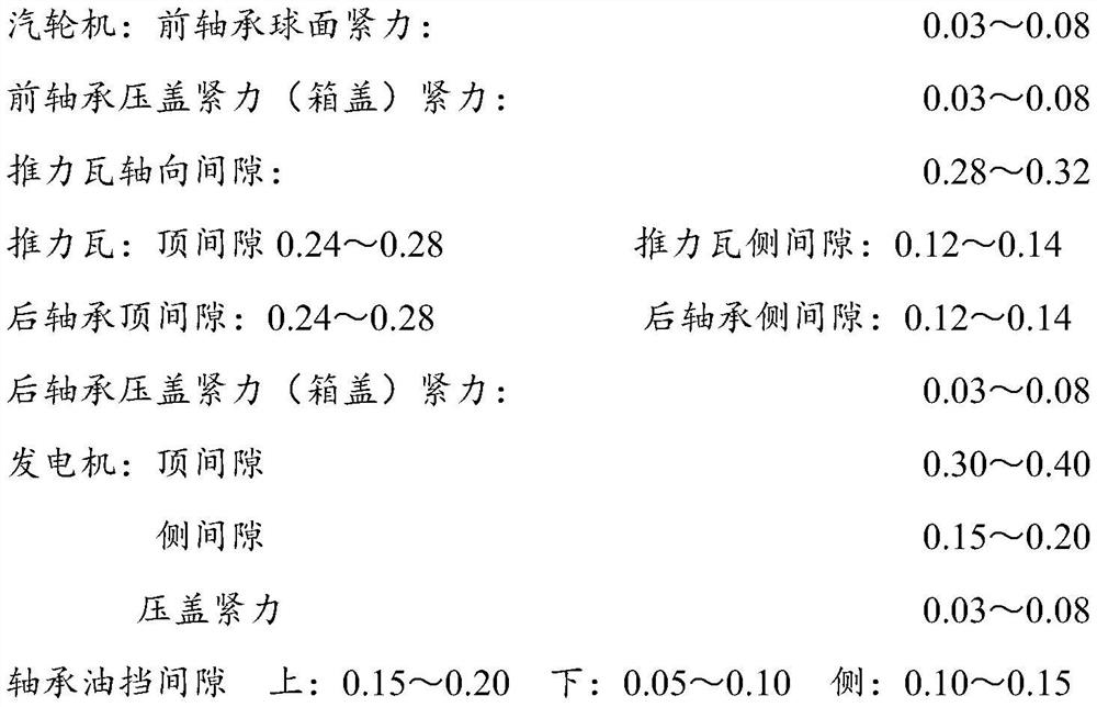
[0089] On the basis of Example 1, the measured values ​​of bearing pad tightening force, bearing pad top clearance, shaft seal clearance and bearing pad side clearance should meet the following requirements:

[0090]

[0091] The above units are mm.


PUM


Abstract

The invention discloses a steam turbine unit mounting technology, and belongs to the technical field of steam turbine mounting. The problems that in the prior art, the quality of a steam turbine unit mounting technology is difficult to control, and consequently frequent maintenance is caused is solved. The steam turbine unit mounting technology comprises the following steps of technological preparation, sizing block arrangement, front bearing seat mounting, lower cylinder mounting, partition plate mounting, rotor mounting, cylinder longitudinal and transverse horizontal correction, pre-buckling of a large cover on a steam turbine, generator bearing mounting, generator bearing seat mounting, generator rotor checking and hoisting, coaxiality aligning of the steam turbine and a generator, generator stator bedplate mounting, generator stator mounting, generator rotor penetrating, air gap and magnetic center adjusting, bearing bush gap and tightening force adjusting of a steam turbine and generator unit, buckling of the large cover on the steam turbine, secondary grouting of the unit, cleaning, checking and re-mounting of a speed regulating system, bearing box covering, turning gear mounting and adjusting and grouting. According to the technology, the quality of the technological process is strictly controlled, and the stability and safety of the technology are remarkably improved.

Description

technical field [0001] The invention belongs to the technical field of steam turbines, and in particular relates to a steam turbine unit installation process. Background technique [0002] The steam turbine, also known as the steam turbine engine, is a rotary steam power device. The high-temperature and high-pressure steam passes through the fixed nozzle to become an accelerated air flow and then sprays onto the blades, so that the rotor equipped with blade rows rotates and works externally. Steam turbines are the main equipment of modern thermal power plants, and are also used in metallurgical industry, chemical industry, and ship power plant. [0003] According to the working principle, steam turbines are divided into impulse steam turbines and reaction steam turbines: [0004] (1) The steam of the impulse turbine mainly expands in the stationary blades, and only a small amount expands in the moving blades. [0005] (2) The steam of the reaction steam turbine expands in ...

Claims


Application Information

Patent Timeline
Patent Type & Authority Applications(China)
IPC IPC(8): B23P19/00B23P19/10B23P21/00
CPCB23P21/00B23P19/001B23P19/10
Inventor 周刚熊凯凌僖钞黎波傅伟
Owner 四川华川基业建设集团有限公司
Learn More