Environment-friendly concentrating machine
A kind of ore concentrator and environmental protection technology, applied in the direction of dryer, filter screen, grille, etc., can solve the problems of low classification efficiency, uneven ore feeding, dust removal effect and large vibration of the machine, so as to improve the effect and avoid dust flying , the effect of reducing vibration
- Summary
- Abstract
- Description
- Claims
- Application Information
AI Technical Summary
Problems solved by technology
Method used
Image
Examples
Embodiment 1
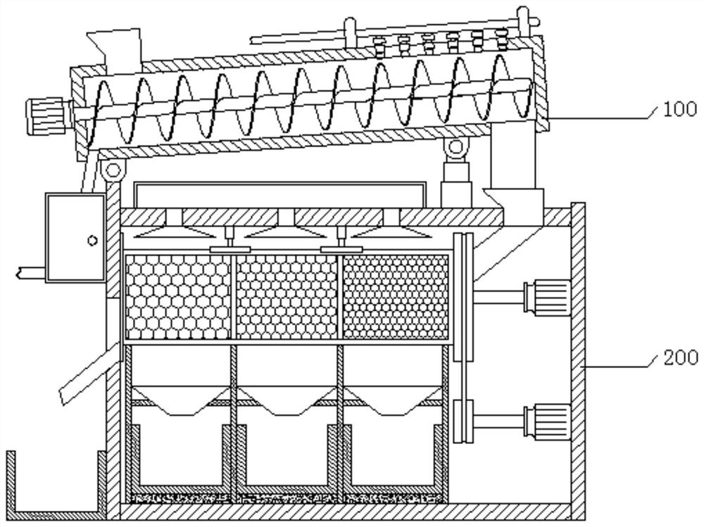
[0041] see figure 1 , the present invention provides a technical solution: an environmentally friendly concentrator, including a dust removal mechanism 100 and a sorting mechanism 200 .
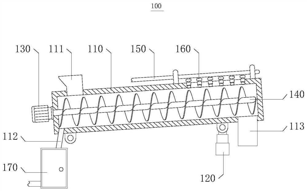
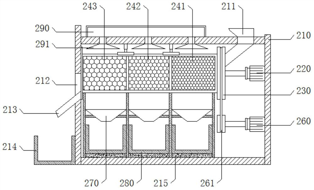
[0042] see figure 2 , the dust removal mechanism 100 includes an installation cylinder 110, an upper hopper 111, a connecting rod 120, a first motor 130, a first auger 140, a water pipe 150 and a nozzle 160, the installation cylinder 110 is installed obliquely, and the upper hopper 111 is inserted into one end of the installation cylinder 110 At the top, the connecting rod 120 is fixedly installed on the bottom of one end of the installation cylinder 110, the first motor 130 is fixedly installed on one end of the installation cylinder 110, the first auger 140 is rotatably installed on the inner wall of the installation cylinder 110 and is keyed to the output shaft of the first motor 130, The water pipe 150 is fixedly installed on the top of the installation cylinder 110, the nozzle 160 is p...
Embodiment 2
[0050] see figure 1 , the present invention provides a technical solution: an environmentally friendly concentrator, including a dust removal mechanism 100 and a sorting mechanism 200 .
[0051] see figure 2 , the dust removal mechanism 100 includes an installation cylinder 110, an upper hopper 111, a connecting rod 120, a first motor 130, a first auger 140, a water pipe 150 and a nozzle 160, the installation cylinder 110 is installed obliquely, and the upper hopper 111 is inserted into one end of the installation cylinder 110 At the top, the connecting rod 120 is fixedly installed on the bottom of one end of the installation cylinder 110, the first motor 130 is fixedly installed on one end of the installation cylinder 110, the first auger 140 is rotatably installed on the inner wall of the installation cylinder 110 and is keyed to the output shaft of the first motor 130, The water pipe 150 is fixedly installed on the top of the installation cylinder 110, the nozzle 160 is p...
Embodiment 3
[0063] see figure 1 , the present invention provides a technical solution: an environmentally friendly concentrator, including a dust removal mechanism 100 and a sorting mechanism 200 .
[0064] see figure 2 , the dust removal mechanism 100 includes an installation cylinder 110, an upper hopper 111, a connecting rod 120, a first motor 130, a first auger 140, a water pipe 150 and a nozzle 160, the installation cylinder 110 is installed obliquely, and the upper hopper 111 is inserted into one end of the installation cylinder 110 At the top, the connecting rod 120 is fixedly installed on the bottom of one end of the installation cylinder 110, the first motor 130 is fixedly installed on one end of the installation cylinder 110, the first auger 140 is rotatably installed on the inner wall of the installation cylinder 110 and is keyed to the output shaft of the first motor 130, The water pipe 150 is fixedly installed on the top of the installation cylinder 110, the nozzle 160 is p...
PUM
 Abstract
Description
Claims
Application Information
 - R&D
- Intellectual Property
- Life Sciences
- Materials
- Tech Scout
- Unparalleled Data Quality
- Higher Quality Content
- 60% Fewer Hallucinations
Browse by: Latest US Patents, China's latest patents, Technical Efficacy Thesaurus, Application Domain, Technology Topic, Popular Technical Reports.
© 2025 PatSnap. All rights reserved.Legal|Privacy policy|Modern Slavery Act Transparency Statement|Sitemap|About US| Contact US: help@patsnap.com


