
Water ring type vacuum pump efficiency improving device and control method

A water ring vacuum pump and control system technology, applied in the direction of rotary piston pumps, pumps, machines/engines, etc., can solve the problems that affect the negative pressure of the unit, the efficiency of the vacuum pump decreases, and the sealing water of the vacuum pump cannot achieve effective cooling, etc.

Pending Publication Date: 2021-07-06
HUANENG POWER INTERNATIONAL
View PDF0 Cites 0 Cited by
  • Summary
  • Abstract
  • Description
  • Claims
  • Application Information

AI Technical Summary

Problems solved by technology

However, due to the limitations of the design conditions of the water ring vacuum pump itself and the site conditions, when the temperature of the sealing water in the vacuum pump body rises due to mechanical work, friction, heat transfer, etc., the sealing water on the suction and exhaust end faces of the pump body will vaporize, and the efficiency of the vacuum pump will be reduced. Serious decline, but the closed cooling water or open cooling water used as the sealing water cooling water of the vacuum pump is limited by the environmental conditions, and the temperature in summer is high. Taking a power plant on the shore of Bohai Bay as an example, the seawater temperature reaches 30°C in summer. It is used as the working fluid of the vacuum pump to cool The temperature of the closed cooling water of the water reaches 33°C, which causes the sealing water of the vacuum pump to be unable to achieve effective cooling, and the efficiency of the vacuum pump decreases, which in turn affects the negative pressure of the unit

Method used


Image

  • Water ring type vacuum pump efficiency improving device and control method
  • Water ring type vacuum pump efficiency improving device and control method
  • Water ring type vacuum pump efficiency improving device and control method

Examples


Embodiment Construction

[0026] In the following, embodiments of the present invention will be described below, and those skilled in the art can easily understand other advantages and efficacy of the present invention, apparently, as described in the present invention. , Not all of the embodiments. Based on the embodiments of the present invention, there are all other embodiments obtained without making creative labor without making creative labor premises.

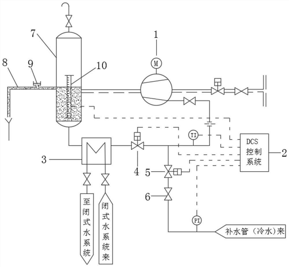
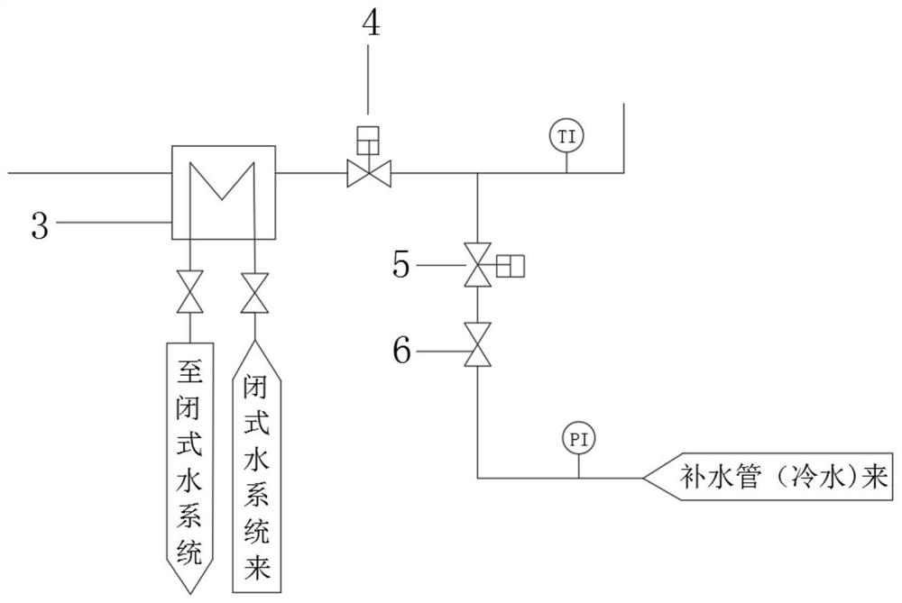
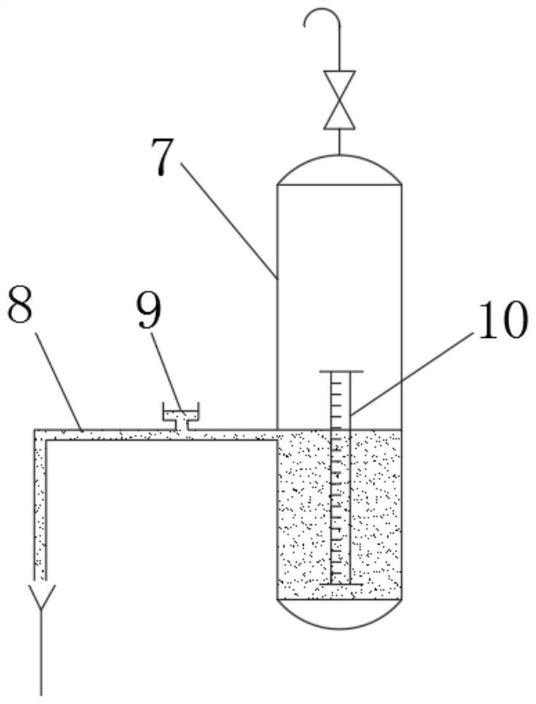
[0027] The technical solution uses a fire power plant using reservoir deep water as a vacuum pump cold water hydration water source as an example: refer to the instructions Figure 1-3 The present invention provides a water ring vacuum pump promotion device including a water loop vacuum pump 1 and a DCS control system 2, and the cold water hydrating pipe is fixed on the rear pipe 3 of the sealed water cooler 3 of the water ring vacuum pump 1. The tube introduces sealing water water hydration water source, and the cold water hydrating pipe is fixed to ...


PUM

PropertyMeasurementUnit
Diameteraaaaaaaaaa
Diameteraaaaaaaaaa

Abstract

The invention discloses a water ring vacuum pump efficiency improving device and a control method, and particularly relates to the field of industrial machinery. The water ring vacuum pump efficiency improving device comprises a water ring vacuum pump and a DCS control system; a cold water supplementing pipe is fixed to a rear pipeline of a sealing water cooler of the water ring vacuum pump, and a sealing water cold water supplementing water source is introduced through the cold water supplementing pipe; a sealing water pneumatic normal water supplementing valve is fixed on the cold water supplementing pipe; a temperature sensor is arranged behind the sealing water pneumatic normal water supplementing valve; a pneumatic cold water supplementing valve is fixed on the cold water supplementing pipe; a manual stop valve is arranged behind the pneumatic cold water supplementing valve; and a pressure sensor is arranged on a pipeline in front of the pneumatic cold water supplementing valve. The operation state of the water ring vacuum pump can be comprehensively and effectively judged, once the system breaks down, the normal operation mode can be rapidly switched, or the water ring vacuum pump is interlocked and stopped, and the operation safety of the whole unit is guaranteed.

Description

Technical field [0001] Embodiments of the present invention relate to the field of industrial machinery, specifically involving a water loop vacuum pump efficiency device and a control method, suitable for a fire-powered power generating enterprise installed as a water ring vacuum pump as a negative pressure system suction tool, is also suitable for installation of water Electricity, metallurgy, steel, petrochemical, refining and other industries of ring vacuum pump. Background technique [0002] A large amount of fire-generating industry is used as a water loop vacuum pump as a negative pressure system to start the vacuum settled suction tool and will continue to extract the non-condensing gas in the negative pressure system during operation, maintain a high vacuum of the negative pressure system, improve the overall thermal cycle efficiency. Reducing power generation coal consumption, as an example of 600MW of vertical fire power unit, the negative pressure system vacuum increa...

Claims


Application Information

Patent Timeline
IPC IPC(8): F04C19/00F04C25/02F04C28/28
CPCF04C19/00F04C19/004F04C25/02F04C28/28
Inventor 刘平升张忠华杨志佳王峰林旭宏
Owner HUANENG POWER INTERNATIONAL
Learn More