Rotary gate with position convenient to adjust

A rotary type, gate technology, applied in ship locks, ship lifting devices, water conservancy projects, etc., can solve the problems of large-span ship lock gates with heavy weight, inconvenience, and high investment in construction and equipment

Active Publication Date: 2021-07-06
ZHEJIANG PROVINCIAL INST OF COMM PLANNING DESIGN & RES CO LTD
View PDF14 Cites 0 Cited by
  • Summary
  • Abstract
  • Description
  • Claims
  • Application Information

AI Technical Summary

Problems solved by technology

Its disadvantages: For large-span ship lock gates, in order to reduce energy consumption, balance weights are installed on both sides of the machine room, the building height of the machine room is not in harmony with the surrounding landscape, the seismic performance is poor, and the investment in construction and equipment is relatively high
Although this kind of gate can realize navigation and flood control, it still has shortcomings: the arc gate is limited by the hydraulic cylinder, the structure of the support arm is not stable, and the structural reliability is poor; It is inconvenient to change the connection position of the support arm

Method used


Image

  • Rotary gate with position convenient to adjust
  • Rotary gate with position convenient to adjust
  • Rotary gate with position convenient to adjust

Examples


Embodiment 1

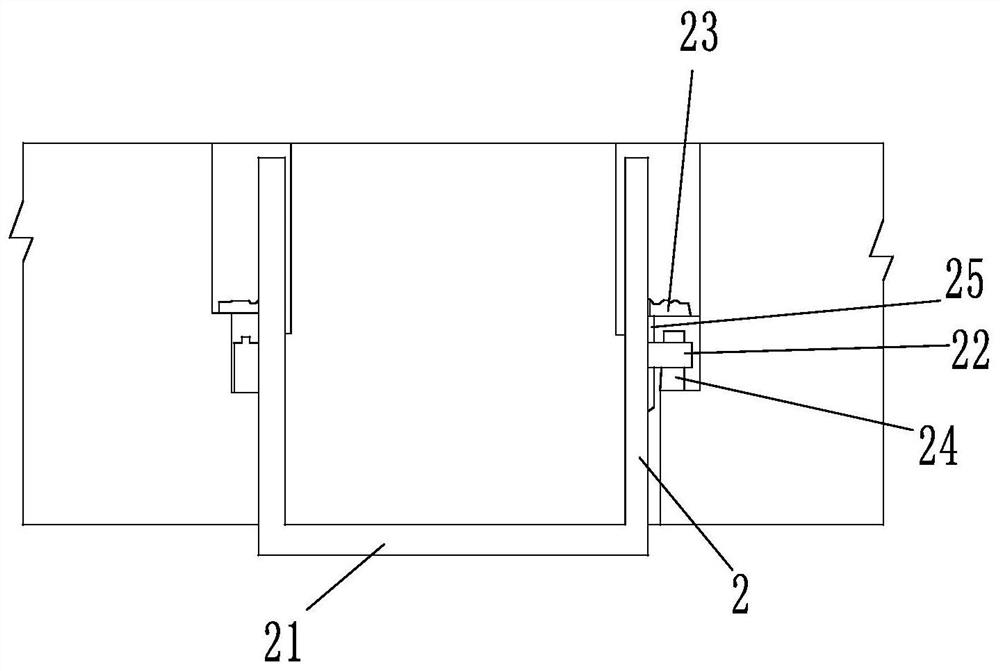
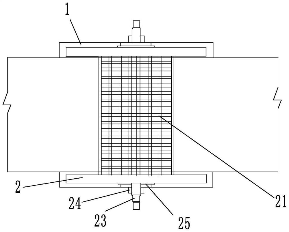
[0028] Such as Figure 1 to 3 As shown, a rotating gate that is convenient for adjustment is located between the two opposite gate walls 1, including two coaxial opposing control disc 2, control disc 2 is cylindrical, two control disc 2 The side connection is provided with a curved door leaf 21, and the radial cross-sectional shape of the curved door leaf 21 is an arcuate. The outer side of the curved door leaf 21 and the peripheral side of the control disc 2 are coincident. The center angle of the outer radial cross section of the curved door leaf 21 is between 60 degrees and 75 degrees, and 67.5 degrees in the examples are employed. The secondary side of the two control disc 2 is provided with a connecting shaft 22, and the connecting shaft 22 is connected to the shutter 23; the connecting shaft 22 and the shutter 23 are disposed on the gate wall 1, and the gate wall 1 is provided with a mating connection axis. The support 24 of the 22, the connecting shaft 22 is provided with a ...

Embodiment 2

[0030] A rotating gate that is convenient for adjustment, such as Figure 6 with Figure 7As shown, in Example 2 and Example 1 showed that the top positioning mechanism located on the side surface of the control disc 2 was increased. The gate wall 1 is expanded in the cavity region of the control disc 2, and the opposite side of the two control disc 2 is provided with a limit tooth 4 provided inward from the outer periphery, and the limit teeth 4 are located in one and control. On the conical surface of the disc 2 coaxially, the gate wall 1 is provided with a top-tightening positioning mechanism in which the disc 2 is connected, and the top positioning mechanism includes a first fixing ring 41 and the second in the outer side of the control disc 2. The fixing ring 42, the first fixing ring 41 is provided with several fixing holes, and four fixed holes are provided, and the self-locking screw 43 is also provided with four; the shape of the first fixing ring 41 is rounded square, the ...


PUM


Abstract

The invention discloses a rotary gate with a position convenient to adjust. The gate is located between two opposite lock walls and comprises two control discs which are coaxially and oppositely arranged, the sides, opposite to each other, of the two control discs are connected with arc-shaped gate leaves, the sides, away from each other, of the two control discs are provided with connecting shafts correspondingly, and the connecting shafts are connected with a hoist; the connecting shafts and the hoist are arranged on the lock walls, and a bottom sill matched with the shape of the outer sides of the arc-shaped gate leaves is arranged between the two lock walls. The gate has the beneficial effects that the multifunctional switching among flood control, navigation and flood discharge can be realized, the safety is high, the limiting effect is reliable, and the position adjustment of the gate is more convenient; and the gate has high tidal bore prevention capacity and is stable and reliable in structure.

Description

Technical field [0001] The present application relates to the technical field of water conservancy gates, and in particular, a rotating gate that is convenient for adjustment. Background technique [0002] Domestic Navigation Ship Locks can use vertical improvement plane doors that can be used navigives and will block the tide. Its advantageous gate structure is simple, and the side beam is embedded into the doorway, which can resist the hurt impact and safe and reliable. Its disadvantage: For the large span boat gate, in order to reduce the energy consumption, the balance weight on both sides of the machine room is set, the height of the machine room is not coordinated with the surrounding landscape, poor seismic performance, the investment of buildings and equipment is relatively high. Although the horizontal rotating triangle door can withstand the two-way head, the moving water is closed and closed, and it cannot be stopped, and the safety is poor. Although the arc of the ver...

Claims


Application Information

Patent Timeline
Patent Type & Authority Applications(China)
IPC IPC(8): E02B7/42E02C1/00
CPCE02B7/42E02C1/00Y02A10/30
Inventor 翟继民
Owner ZHEJIANG PROVINCIAL INST OF COMM PLANNING DESIGN & RES CO LTD
Why Eureka
Try Eureka