
Main landing gear of airplane

A landing gear and aircraft technology, which is applied in the field of aircraft take-off and landing systems, can solve the problems of large bending moment deformation, wheel jump, and low absorption efficiency of the landing gear buffer system.

Pending Publication Date: 2021-07-06
北摩高科正定摩擦材料有限公司
View PDF1 Cites 0 Cited by
  • Summary
  • Abstract
  • Description
  • Claims
  • Application Information

AI Technical Summary

Problems solved by technology

[0004] The above-mentioned existing technologies have technical problems such as low absorption efficiency of the landing gear buffer system, wheel jumping, deformation under large bending moments, etc.

Method used


Image

  • Main landing gear of airplane
  • Main landing gear of airplane
  • Main landing gear of airplane

Examples


Embodiment

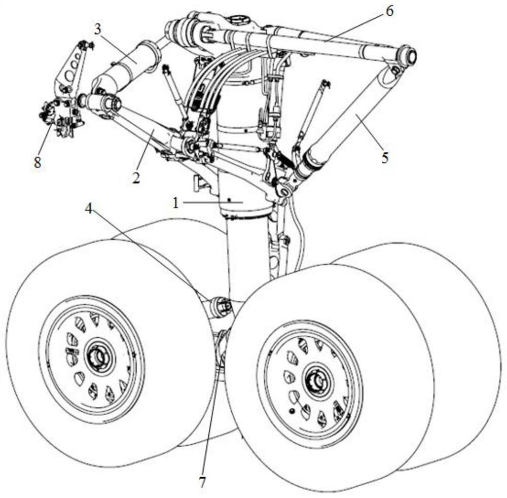
[0036] Such as figure 1 As shown, the main landing gear of the aircraft includes a buffer pillar 1, a foldable strut with a lock 2, a retractable actuator 3, a stabilizing buffer 4, a diagonal strut 5, a front strut 6, a wheel set 7 and Uplock 8;

[0037] The buffer strut 1 is respectively connected to the retractable actuator 3, the foldable strut with lock 2, the stable buffer 4, the front strut 6, the diagonal strut 5 and the wheel Group 7;

[0038] The upper lock 8, the retractable actuator 3, the foldable strut 2 with lock, the buffer strut 1 and the front strut 6 are all connected to the joint of the aircraft fuselage;

[0039] The stabilizing buffer 4 is connected to the wheel set 7 .

[0040] In the above embodiment, the buffer pillar 1 is provided with joints respectively connected with the retractable actuator 3 and the foldable strut 2 with lock, and the buffer pillar 1 is provided with joints connected with the diagonal brace respectively. The double-ear seat c...


PUM


Abstract

The invention discloses a main landing gear of an airplane. The main landing gear comprises a buffer supporting column, a foldable supporting rod with a lock, a retracting and releasing actuating cylinder, a stable buffer, an inclined supporting rod, a front supporting rod, an airplane wheel set and an uplock, the buffering supporting column is connected to the retracting and releasing actuating cylinder, the foldable supporting rod with the lock, the stable buffering device, the front supporting rod, the inclined supporting rod and the airplane wheel set. The uplock, the retracting and releasing actuating cylinder, the foldable supporting rod with the lock, the front supporting rod and the buffering supporting column are all connected to an aircraft body connector. The stable buffer is connected to the airplane wheel set; and the inclined supporting rod is connected to the front supporting rod. According to the main landing gear of the aircraft, vertical kinetic energy generated when the aircraft lands can be better absorbed, and the efficiency coefficient is improved; and impact caused by course load is buffered.

Description

technical field [0001] The invention belongs to the technical field of aircraft take-off and landing systems, and in particular relates to an aircraft main landing gear. Background technique [0002] At present, the domestic multi-wheel main landing gear development technology is not good enough, and it still stays at the design and production level in the 1960s. When a large aircraft lands, the buffer system cannot absorb the vertical kinetic energy well (low absorption efficiency, etc.), The jumping of the front and rear wheels causes a large ground load to be transmitted to the aircraft fuselage through the landing gear, which affects the safety of the aircraft; The strength and life of the key technologies are discounted. Usually, the aircraft needs to replace multiple sets of landing gear during its service life. Therefore, solving the above problems to improve the strength and life of the landing gear has been put on the agenda by researchers. [0003] For example, th...

Claims


Application Information

Patent Timeline
Patent Type & Authority Applications(China)
IPC IPC(8): B64C25/58B64C25/22B64C25/26
CPCB64C25/58B64C25/22B64C25/26
Inventor 张天闯王少宁刘志伟杨昌坤王岩宁丁丁和文昭王德华赵锤赵新纯
Owner 北摩高科正定摩擦材料有限公司
Learn More