Instrument for grafting bones in lesion vertebral body of percutaneous vertebral pedicle
A pedicle and bone grafting technology, applied in the direction of internal fixator, internal bone synthesis, fixator, etc., can solve the problems of aggravated kyphosis, loss of vertebral body, failure of internal fixation, etc.
- Summary
- Abstract
- Description
- Claims
- Application Information
AI Technical Summary
Problems solved by technology
Method used
Image
Examples
Embodiment 1
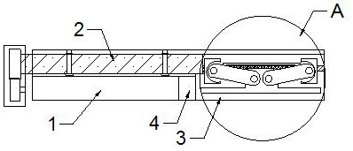
[0045] combine Figure 1-8 A percutaneous pedicle bone grafting instrument for diseased vertebrae includes a bone grafting mechanism and a driving mechanism for driving the bone grafting mechanism, and the bone grafting mechanism is driven by the driving mechanism to perform bone grafting to a bone defect.
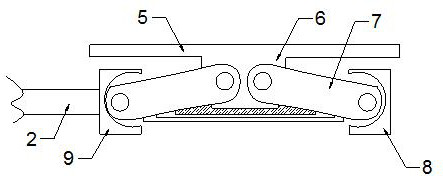
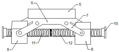
[0046] The bone grafting mechanism includes a bone grafting cylinder 1, a screw rod 2 and a pusher assembly, wherein the bone grafting cylinder 1 is a hollow cylindrical structure with two ends open, and one end of the bone grafting cylinder 1 is provided with an inwardly recessed bone grafting The bin 3, the bone graft bin 3 is not connected to the hollow tube of the bone graft tube 1, and the side of the bone graft tube 1 facing the bottom of the bone graft bin 3 is provided with a sub-tube for encapsulating the screw rod 2, and the screw rod 2 passes through the bearing The seat is connected with the inner side wall of the sub-tube, the screw mandrel 2 is rotationally con...
Embodiment 2
[0054] combine Figure 9 , the drive mechanism includes an adjustment wheel 14 located at the end of the screw rod 2 away from the pusher assembly, the adjustment wheel 14 is connected to the axis of the screw rod 2 coincidently, and the outer periphery of the adjustment wheel 14 is connected by a toothed groove. The driving wheel 15 driven by the motor 16, the output shaft of the motor 16 coincides with the axis of the driving wheel 15 and is connected, the driving mechanism is sealed in the control box, and the control box is sealed and connected with the screw mandrel, A control button for driving the motor is provided, the gear is manual or electric, and a scale is provided on the outer wall of the bone grafting cylinder.
[0055] The motor of the driving mechanism drives the driving wheel to rotate, so that the adjusting wheel meshed with the driving wheel rotates to drive the rotation of the screw rod. The rotation precision of the motor drive is controllable, so that th...
Embodiment 3
[0057] combine Figure 10 , the end of the bone graft cylinder 1 away from the bone graft chamber 3 is also provided with an adjustment mechanism for adjusting the height of the bone graft cylinder 1 .
[0058] The adjustment mechanism includes a positioning rod 18 sleeved on the outer periphery of the bone graft cylinder 1 and a support rod 17 located at the upper end of the bone graft cylinder 1. The positioning rod 18 fixes the outer wall of the bone graft cylinder 1 to the In the positioning sleeve 19, the support rod 17 is connected with a fixed rod 21 for fixing the gear towards the bottom of the positioning rod 18, and the top of the positioning rod 18 is connected with a tooth rack 22 which is space-displaced with the fixed rod 21 and arranged towards the top of the support rod 17. , the fixed rod 21 and the rack 22 are connected by a gear 23, and the distance between the fixed rod 21 and the rack 22 is adjusted by the rotation of the gear 23. Between the positioning r...
PUM
| Property | Measurement | Unit |
|---|---|---|
| Maximum pull | aaaaa | aaaaa |
| Hardness | aaaaa | aaaaa |
Abstract
Description
Claims
Application Information
 - R&D Engineer
- R&D Manager
- IP Professional
- Industry Leading Data Capabilities
- Powerful AI technology
- Patent DNA Extraction
Browse by: Latest US Patents, China's latest patents, Technical Efficacy Thesaurus, Application Domain, Technology Topic, Popular Technical Reports.
© 2024 PatSnap. All rights reserved.Legal|Privacy policy|Modern Slavery Act Transparency Statement|Sitemap|About US| Contact US: help@patsnap.com


