High source voltage outdoor anti-ultraviolet large creepage insulator equipment and production process

An anti-ultraviolet, insulator technology, applied in insulators, circuits, electrical components, etc., can solve problems such as unfavorable installation, inconsistent, large quality, etc., to reduce friction, prevent external interference, and improve service life.

Active Publication Date: 2021-11-05
包兆平
View PDF9 Cites 0 Cited by
  • Summary
  • Abstract
  • Description
  • Claims
  • Application Information

AI Technical Summary

Problems solved by technology

[0002] Insulators are devices installed between conductors of different potentials or between conductors and grounding components that can withstand voltage and mechanical stress. Commonly used insulator materials include ceramics and composite materials, all of which have excellent insulation effects. Ceramic insulators The service life is much longer than that of composite material insulators, but its mass is large, which is not conducive to outdoor installation, especially on high-voltage electric towers. Composite material insulators are widely used on outdoor high-voltage electric towers because of their light weight, but composite material The outer side of the insulator will age faster than the lower side when exposed to the wind and the sun, and needs to be replaced after aging. The purpose of this invention is to solve the problem of different aging speeds on both sides of the insulator of the composite material, thereby prolonging the life of the composite material. The service life of the insulator

Method used


Image

  • High source voltage outdoor anti-ultraviolet large creepage insulator equipment and production process
  • High source voltage outdoor anti-ultraviolet large creepage insulator equipment and production process
  • High source voltage outdoor anti-ultraviolet large creepage insulator equipment and production process

Examples


Embodiment Construction

[0051] The technical solutions in the embodiments of the present invention will be clearly and completely described below with reference to the accompanying drawings in the embodiments of the present invention. Obviously, the described embodiments are only a part of the embodiments of the present invention, but not all of the embodiments. Based on the embodiments of the present invention, all other embodiments obtained by those of ordinary skill in the art without creative efforts shall fall within the protection scope of the present invention.

[0052]In the description of the present invention, it should be understood that the terms "center", "longitudinal", "lateral", "length", "width", "thickness", "upper", "lower", "front", " rear, left, right, vertical, horizontal, top, bottom, inside, outside, clockwise, counterclockwise, etc., or The positional relationship is based on the orientation or positional relationship shown in the drawings, which is only for the convenience o...


PUM


Abstract

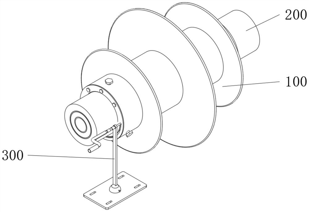
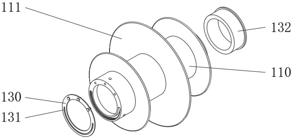
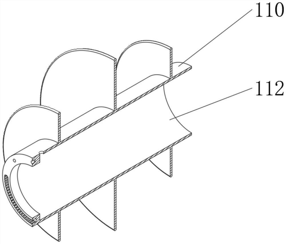
The invention relates to the technical field of electric power transmission, in particular to a high source voltage outdoor anti-ultraviolet large creepage distance insulator equipment and a production process. It includes an outer sheath, an insulating rod located in the outer sheath and a turning device located outside the insulating rod. The outer sheath includes a round sleeve, and the upright outer part of the round sleeve is provided with an apron. There is a connecting block in front of the round sleeve, and the connecting block There is a chute on the outside, the chute is in a semi-circular structure, internal teeth are provided on the inner wall of the chute, the insulating rod includes a first insulator, the first insulator is inserted into the circular sleeve, and a pair of bearings are arranged on the outside of the first insulator. The inner ring is clamped on the outer wall of the first insulator, and the radius of the outer ring of the bearing matches the inner wall radius of the circular sleeve. The purpose of this invention is to solve the problem of different aging speeds on both sides of the insulator of the composite material, thereby prolonging the life of the composite material. The service life of insulators.

Description

technical field [0001] The invention relates to the technical field of power transmission, in particular to a high-source voltage outdoor anti-ultraviolet and large creepage distance insulator equipment and a production process. Background technique [0002] Insulators are devices installed between conductors of different potentials or between conductors and grounding components that can withstand voltage and mechanical stress. Commonly used insulator materials include ceramics and composite materials, all of which have excellent insulating effects. Ceramic insulators The service life is much longer than that of composite insulators, but its mass is large, which is not conducive to outdoor installation, especially on high-voltage towers. Composite insulators are widely used in outdoor high-voltage towers because of their lightness. The outer side of the insulator will age faster than the lower side when it is exposed to the wind and the sun, and it needs to be replaced after...

Claims


Application Information

Patent Timeline
Patent Type & Authority Patents(China)
IPC IPC(8): H01B17/40H01B17/54H01B19/00
CPCH01B17/40H01B17/54H01B19/00
Inventor 胡天凤生胡华庆
Owner 包兆平
Why Eureka
Try Eureka