
Rubber-covered wire optical cable easy to strip

A technology for a sheathed optical cable and an optical fiber unit, which is applied in the field of easy-to-peel sheathed optical cables, can solve the problems of large bonding force, inconvenient connection operation, and difficult peeling of the sheath, and achieves convenient connection operation, improved stripping performance, and improved strippability. Effect

Active Publication Date: 2021-07-02
YANGTZE OPTICAL FIBRE & CABLE CO LTD
View PDF6 Cites 1 Cited by
  • Summary
  • Abstract
  • Description
  • Claims
  • Application Information

AI Technical Summary

Problems solved by technology

However, in the actual production and preparation process, since the sheath is directly extruded and coated on the optical fiber unit, the adhesion between the sheath and the optical fiber is good, and the bonding force is strong; and the vicinity of the optical fiber unit is a continuous single resin phase, which is stripped by the outside. When the force is applied, the peeling force is transmitted slowly in the resin phase, causing the sheath to be difficult to peel off; at the same time, in order to avoid the pressure of the optical fiber unit and the cracking of the sheath, the "groove" or "V-groove" is usually designed to be shallow; the above Many factors make the existing 8-shaped leather cable not easy to be torn and stripped, which not only brings inconvenience to the splicing operation, but also easily causes damage to the optical fiber unit and defects such as "broken fiber" during the sheath stripping process

Method used


Image

  • Rubber-covered wire optical cable easy to strip
  • Rubber-covered wire optical cable easy to strip
  • Rubber-covered wire optical cable easy to strip

Examples


Embodiment 1

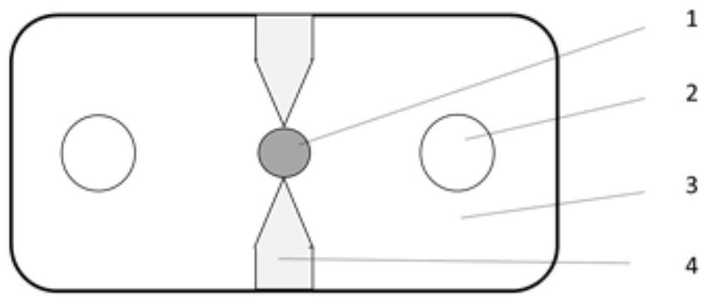
[0021] The structure of embodiment 1 is as figure 1 As shown, it includes a sheath 3 with a rectangular cross-section, and an optical fiber unit 1 is coated in the middle of the sheath. The optical fiber unit is a single-core optical fiber, and the number of cores can be 1 core. The corresponding optical fiber units on both sides of the sheath A reinforcing member is installed symmetrically, the reinforcing member is GRP, and a groove shrinking from the outside to the inside is arranged symmetrically in the upper and lower middle of the sheath corresponding to the optical fiber unit. , that is, the top is square and the lower part is V-shaped. The V-shaped bottom of the groove reaches or approaches the optical fiber unit to form a deep groove. The distance between the apex of the V-shaped bottom of the deep groove and the surface of the optical fiber unit is 0.1 ~0.2mm. The described deep groove is filled with a separation filling layer 4, and the resin material of the separa...

Embodiment 2

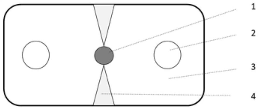
[0023] The structure of embodiment 2 is as figure 2 As shown, the difference between its structure and Embodiment 1 is that the deep groove is V-shaped in the transverse section of the sheath, the optical fiber unit is a single-core optical fiber, and the number of cores can be 2 cores, so The reinforcements described above are steel wires, and the rest of the structures are the same. The resin material of the separation filling layer is different from the resin material of the sheath, wherein the resin material of the sheath has a solubility parameter of 18.1 (J / cm 3 ) 0 . 5 The flame-retardant LSZH, the resin material of the separation filling layer has a solubility parameter of 20.1 (J / cm 3 ) 0 . 5 Polyacrylate flame retardant resin, polyacrylate flame retardant resin components and content by weight: polyacrylic acid 50%, ATH44%, organic expanded nano-soil 2%, antioxidant 1%, anti-UV agent 2%, White toner 1%.

[0024] The manufacturing process of the present embo...

Embodiment 3

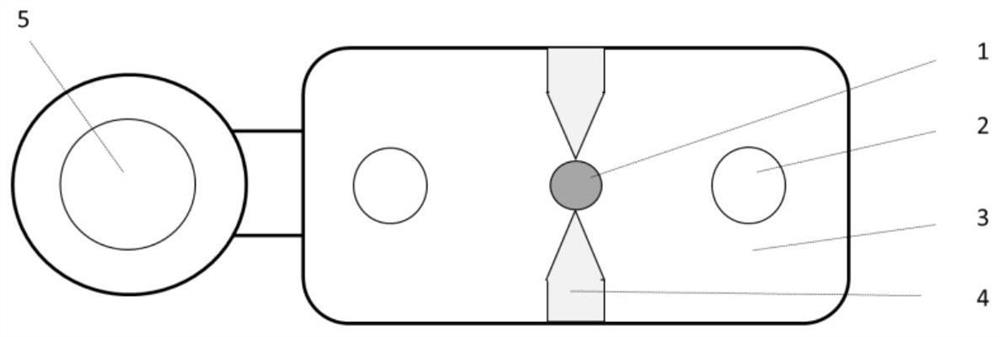
[0025] The structure of embodiment 3 is as image 3 As shown, the difference between its structure and embodiment 1 is that the steel wire sling 5 is connected by a connecting belt on one side of the sheath, the steel wire sling includes a steel wire and an outer sheath, and the outer sheath is integrated with the connecting sling and the sheath. All the other structures are the same as in Example 1. The resin material of the separation filling layer is different from the resin material of the sheath, wherein the resin material of the sheath has a solubility parameter of 19.2 (J / cm 3 ) 0 . 5 Flame-retardant PVC, the resin material of the separation filling layer has a solubility parameter of 17.5 (J / cm 3 ) 0 . 5 The polyethylene flame retardant resin, polyethylene flame retardant resin components and content by weight are: polyethylene 44%, MTH 50%, organic expanded nano-soil 2%, antioxidant 1%, anti-UV agent 3%.

[0026] The production process of this embodiment is as...


PUM


Abstract

The invention relates to a rubber-covered wire optical cable easy to strip, which comprises a sheath with a rectangular cross section, wherein an optical fiber unit is coated at the middle part in the sheath, reinforcers are arranged at two sides in the sheath and correspond to the optical fiber unit, and grooves contracting from outside to inside are arranged at the middle parts of the upper and lower surfaces outside the sheath corresponding to the optical fiber unit. The optical cable is characterized in that the bottom of the groove reaches or is close to the optical fiber unit to form a deep groove, the deep groove is filled with a separation filling layer, and the resin material of the separation filling layer is different from the resin material of the sheath. According to the invention, when the sheath is subjected to external stress or self-contraction, the top point of the bottom of the groove body extrudes the optical fiber, so that the attenuation of the optical fiber is prevented from being increased; and the stripping performance of the sheath of the rubber-covered wire optical cable is improved, so that the continuous operation is convenient, the fiber protection performance is good, the defect that the sheath is difficult to strip due to bonding of the sheath layer and the optical fiber unit can be avoided, and the phenomena of damage to the optical fiber unit and fiber breakage in the stripping process are avoided.

Description

technical field [0001] The invention relates to an optical cable which is easy to peel off the leather wire, and belongs to the technical field of communication optical fiber and optical cable. Background technique [0002] With the rapid development of Internet technology, optical fiber access has become a hot spot in the field of optical communication. In the optical fiber access project, the indoor wiring close to the user is a relatively complicated link. At present, the general access network often uses a dish-shaped drop-in optical cable, that is, a leather cable. Ordinary leather cable has a standard 8-shaped (butterfly) structure. There are two parallel reinforcing cores in the sheath with a rectangular cross-section, and the middle is an optical fiber; A wire hanging wire. [0003] Usually, in order to improve the peelability of the sheath layer near the optical fiber unit in the covered cable, "grooves" or "V-shaped grooves" are designed symmetrically on the top ...

Claims


Application Information

Patent Timeline
IPC IPC(8): G02B6/44
CPCG02B6/443G02B6/4432G02B6/4436G02B6/566
Inventor 罗俊超杨向荣祁林刘宏超黄杰
Owner YANGTZE OPTICAL FIBRE & CABLE CO LTD
Learn More