
Grease tank utilizing waste heat of hydraulic pipeline

A grease tank, hydraulic pipe technology, applied in the direction of transmission parts, belts/chains/gears, mechanical equipment, etc., can solve the problems of corrosion of the surface of transmission parts, poor fluidity, transportation, etc., to avoid oxidative deterioration, avoid accelerated volatilization, The effect of increasing liquidity

Active Publication Date: 2021-07-02
SAIC VOLKSWAGEN AUTOMOTIVE CO LTD
View PDF10 Cites 0 Cited by
  • Summary
  • Abstract
  • Description
  • Claims
  • Application Information

AI Technical Summary

Problems solved by technology

[0003] It is precisely because of this semi-solid feature that only the grease near the oil suction port of the pump is pumped in the grease tank, and the remaining about 70% of the grease cannot flow to the oil suction port due to insufficient fluidity
At the same time, there is a certain distance between the position of the liquid level sensor and the oil suction port, and it is impossible to detect that there is no grease near the oil suction port, causing the pump to run idly, and the oil is not actually delivered to the lubricating points of the truss manipulator, and even causes severe seizure of the gear and rack Fault
However, due to poor fluidity, some grease far away from the oil suction port has accumulated on the wall of the grease tank for a long time and has not been used, resulting in oxidative deterioration and acidity. After being mixed with the newly added grease, it will be transported to the rack and pinion transmission mechanism, which will corrode the transmission. Surface of the piece

Method used


Image

  • Grease tank utilizing waste heat of hydraulic pipeline
  • Grease tank utilizing waste heat of hydraulic pipeline
  • Grease tank utilizing waste heat of hydraulic pipeline

Examples


Embodiment Construction

[0029] In order to facilitate the understanding of the present invention, the present invention will be described more fully below with reference to the associated drawings. Preferred embodiments of the invention are shown in the accompanying drawings. However, the present invention can be embodied in many different forms and is not limited to the embodiments described herein. On the contrary, these embodiments are provided to make the understanding of the disclosure of the present invention more thorough and comprehensive.

[0030] It should be noted that when an element is referred to as being “fixed” to another element, it can be directly on the other element or there can also be an intervening element. When an element is referred to as being "connected to" another element, it can be directly connected to the other element or intervening elements may also be present. The terms "vertical," "horizontal," "left," "right," and similar expressions are used herein for purposes ...


PUM

PropertyMeasurementUnit
Inclinationaaaaaaaaaa

Abstract

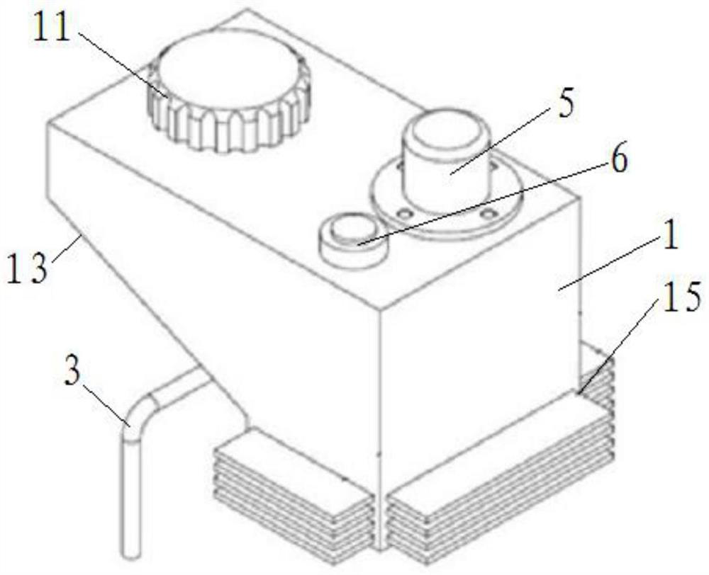
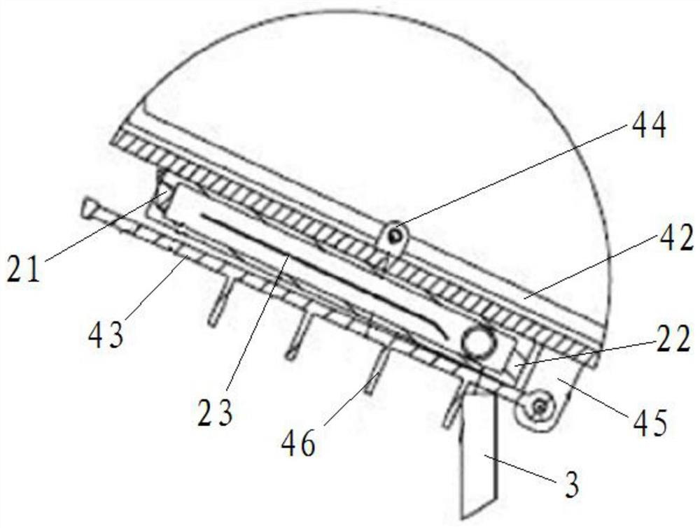
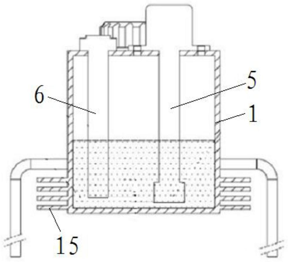
The invention discloses a grease tank utilizing waste heat of a hydraulic pipeline. The grease tank comprises a grease tank body, a water storage tank and a movable heat dissipation connecting rod assembly, wherein the grease tank body is provided with an oil filling port and an oil suction port, the grease tank body is provided with an inclined plane, the inclined plane obliquely extends downwards from the lower part of the oil filling port to the lower part of the oil suction port, the water storage tank is arranged on the outer side face of the inclined face, heat conduction liquid is arranged in the water storage tank, an external hydraulic pipeline extends into the water storage tank, heat is transferred to the inclined face through the heat conduction liquid, the movable heat dissipation connecting rod assembly is arranged on the water storage tank, and the movable heat dissipation connecting rod assembly can conduct contact heat dissipation on the water storage tank or stop heat dissipation on the water storage tank according to the amount of grease in the grease tank body. According to the grease tank, the grease fluidity is improved, grease accumulation and empty suction of an oil suction pump are avoided, meanwhile, accelerated volatilization and grease viscosity rising caused by long-time grease heating can be avoided, and the grease characteristics are guaranteed.

Description

technical field [0001] The invention relates to the technical field of grease tanks, in particular to a grease tank utilizing the residual temperature of a hydraulic pipeline. Background technique [0002] In the prior art, the cylinder head three-line machining production line of an automobile factory generally uses a truss-type manipulator to realize the cylinder head handling and transmission between various processes. The truss-type manipulator is driven by a rack and pinion. The pump transports the lubricating grease in the grease tank to each lubrication point on the truss through the pipeline at intervals. Since the gear rack is an open structure, the lubricating grease is required to be a semi-solid with a certain viscosity, which can be pumped and transported through the pump. , and can adhere to the gear and rack for a long time without loss. [0003] It is precisely because of this semi-solid feature that only the grease near the oil suction port of the pump is e...

Claims


Application Information

Patent Timeline
IPC IPC(8): F16H57/04
CPCF16H57/0413F16H57/0434F16H57/0449F16H57/045F16H57/0464
Inventor 薛飞唐馨张伟李云辉
Owner SAIC VOLKSWAGEN AUTOMOTIVE CO LTD
Learn More