
Device and method for preparing fine-grain wear-resistant layer on surface of railway overhead contact system wire

A technology for conductor surface and catenary, which is applied in the field of devices for preparing fine-grained wear-resistant layers on the surface of railway catenary conductors, can solve the problems of insufficient strength of railway catenary conductors, prolong the service life of catenary conductors, and poor wear resistance. Achieve stable and controllable processing, solve the effect of poor wear resistance and insufficient strength

Active Publication Date: 2021-07-02
EAST CHINA JIAOTONG UNIVERSITY +1
View PDF3 Cites 0 Cited by
  • Summary
  • Abstract
  • Description
  • Claims
  • Application Information

AI Technical Summary

Problems solved by technology

[0006] The purpose of the present invention is to provide a device and method for preparing a fine-grained wear-resistant layer on the surface of a railway catenary wire, so as to solve the above-mentioned problems in the prior art, and can solve the insufficient strength and poor wear resistance of the existing railway catenary wire problem, greatly extending the service life of catenary conductors

Method used


Image

  • Device and method for preparing fine-grain wear-resistant layer on surface of railway overhead contact system wire
  • Device and method for preparing fine-grain wear-resistant layer on surface of railway overhead contact system wire
  • Device and method for preparing fine-grain wear-resistant layer on surface of railway overhead contact system wire

Examples


Embodiment Construction

[0035] The following will clearly and completely describe the technical solutions in the embodiments of the present invention with reference to the accompanying drawings in the embodiments of the present invention. Obviously, the described embodiments are only some, not all, embodiments of the present invention. Based on the embodiments of the present invention, all other embodiments obtained by persons of ordinary skill in the art without making creative efforts belong to the protection scope of the present invention.

[0036] In order to make the above objects, features and advantages of the present invention more comprehensible, the present invention will be further described in detail below in conjunction with the accompanying drawings and specific embodiments.

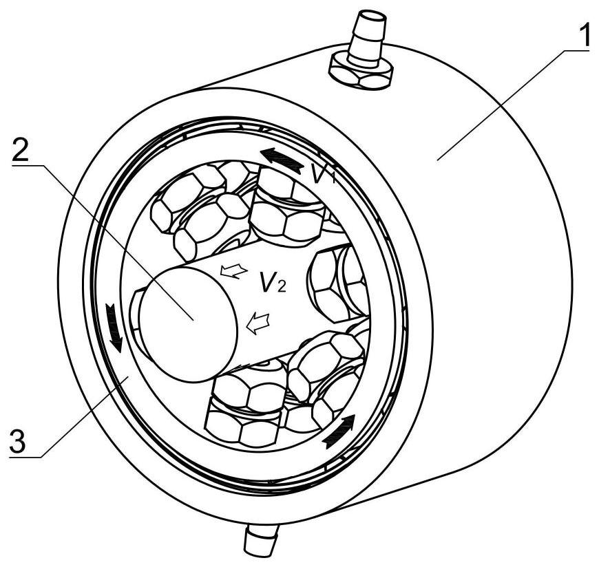
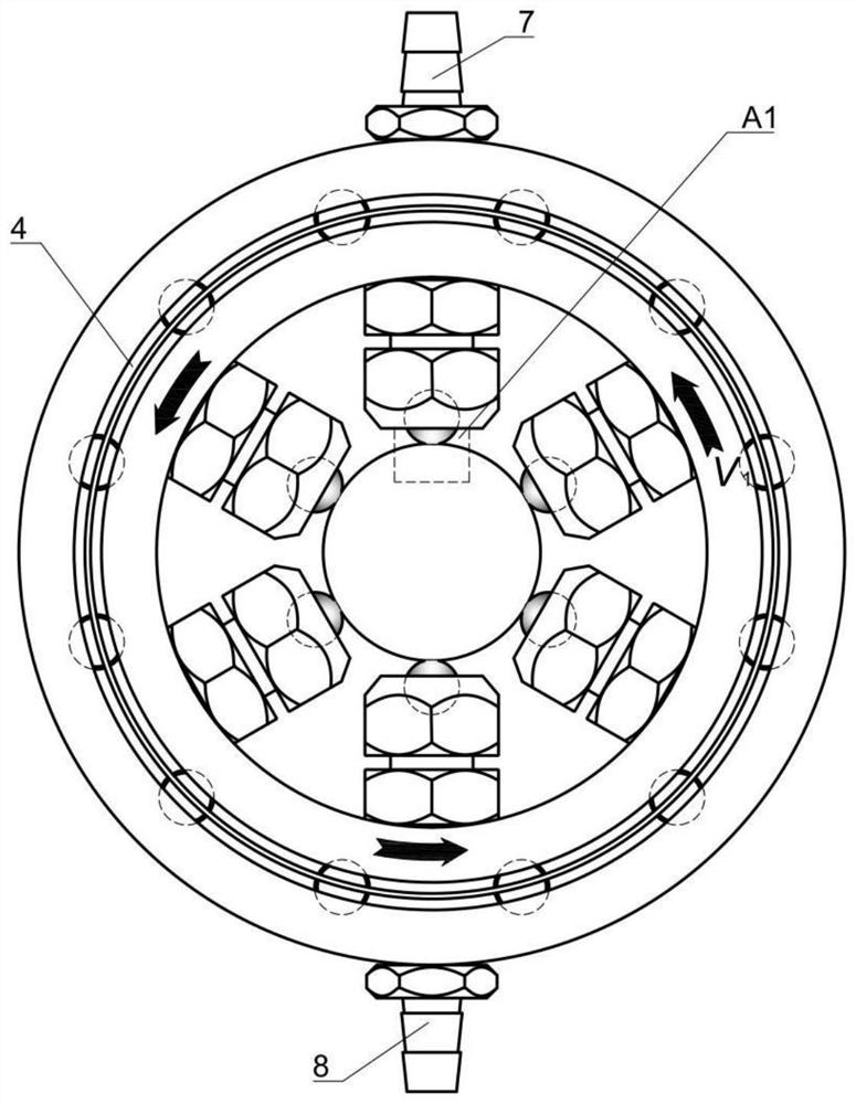
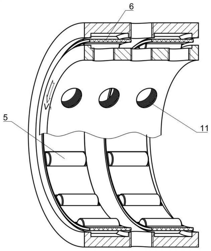
[0037]The invention provides a device for preparing a fine-grained wear-resistant layer on the surface of a railway catenary wire, comprising: a cavity housing 1 and a catenary wire 2; the inner wall of the cavity ...


PUM


Abstract

The invention discloses a device and method for preparing a fine-grain wear-resistant layer on the surface of a railway overhead contact system wire. The device comprises a cavity outer shell and the overhead contact system wire, wherein a first annular groove is circumferentially formed in the inner wall of the cavity outer shell; a cavity inner shell is arranged in the cavity outer shell, a rolling cavity is formed between the cavity outer shell and the cavity inner shell, and a second annular groove is circumferentially formed in the outer wall of the cavity inner shell; a plurality of rolling columns are arranged between the first annular groove and the second annular groove at equal intervals, and a retainer is arranged outside the plurality of rolling columns in a sleeving mode; the outer wall of the cavity outer shell symmetrically communicates with an oil inlet pipe and an oil outlet pipe, and the oil inlet pipe and the oil outlet pipe communicate with the rolling cavity; and a plurality of telescopic rolling cutters are arranged on the inner wall of the cavity inner shell, the ends, connected with the inner wall of the cavity inner shell, of the telescopic rolling cutters communicate with the rolling cavity, and rolling heads are arranged at the other ends of the telescopic rolling cutters. The rolling heads abut against the outer wall of the overhead contact system wire, the problems that an existing railway overhead contact system wire is insufficient in strength and poor in wear resistance can be solved, and the service life of the overhead contact system wire is greatly prolonged.

Description

technical field [0001] The invention relates to the technical field of material processing and surface strengthening of electrified railway components, in particular to a device and method for preparing a fine-grained wear-resistant layer on the surface of a railway catenary wire. Background technique [0002] With the continuous acceleration of railway high-speed, heavy-duty and electrification, the problem of pantograph-catenary relationship in the service process of electrified trains has become more prominent, and the wear and damage of catenary conductors has become increasingly serious, and the service life of catenary conductors has been greatly reduced. However, frequent replacement of catenary conductors is a huge economic burden on railway operations. [0003] At the same time, as a wire for electrified railway catenary, the performance requirements include electrical conductivity, tensile strength, heat softening, fatigue resistance, wear resistance and corrosion ...

Claims


Application Information

Patent Timeline
Patent Type & Authority Applications(China)
IPC IPC(8): C22F1/08
CPCC22F1/08
Inventor 沈明学容康杰肖叶龙季德惠赵火平朴钟宇蔡智超熊光耀
Owner EAST CHINA JIAOTONG UNIVERSITY
Learn More