Multi-light source optical imaging communication system independent of shooting orientation

A technology for optical imaging and communication systems, applied in image communication, short-range systems, components of TV systems, etc., to reduce the impact and achieve simple effects

Active Publication Date: 2022-03-22
JILIN UNIV
View PDF8 Cites 0 Cited by
  • Summary
  • Abstract
  • Description
  • Claims
  • Application Information

AI Technical Summary

Problems solved by technology

Under normal circumstances, multiple LED light sources are mostly arranged symmetrically, but in multi-light source optical imaging communication, the arrangement of symmetrically arranged multi-light sources will cause the same sending device to send the same information due to the shooting orientation, and users in different orientations can analyze receive different information

Method used


Image

  • Multi-light source optical imaging communication system independent of shooting orientation
  • Multi-light source optical imaging communication system independent of shooting orientation
  • Multi-light source optical imaging communication system independent of shooting orientation

Examples


Embodiment Construction

[0033] In order to make the technical solutions and advantages of the present invention clearer, the technical solutions of the present invention will be described completely and clearly below in conjunction with the accompanying drawings in the examples of the present invention. It should be pointed out that if there are any processes or symbols that are not specifically described in detail below, those skilled in the art can refer to the prior art. The key of the present invention lies in the technical solution proposed for the demodulation structure, involving software or programming content Those skilled in the art can refer to existing implementations.

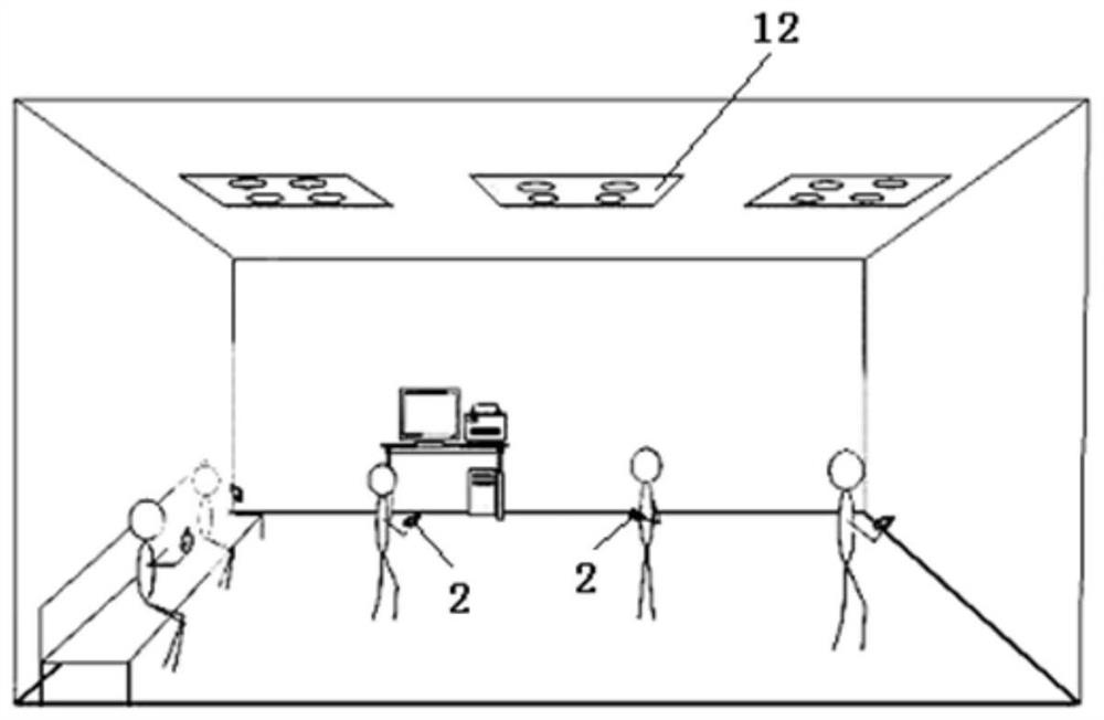
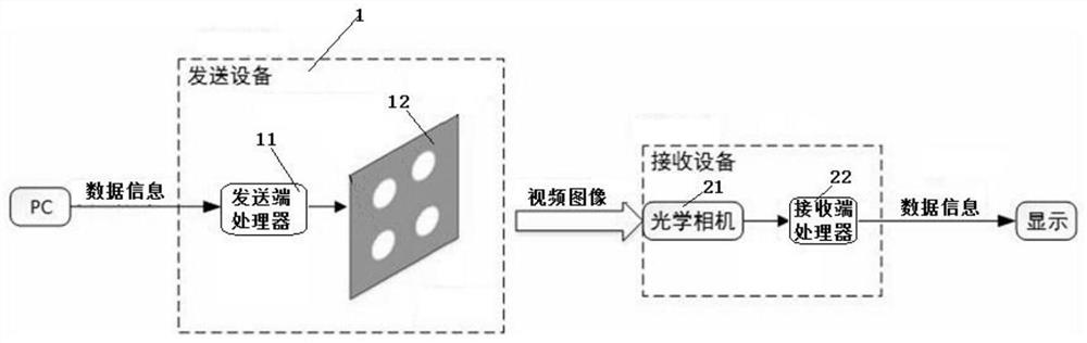
[0034] Such as figure 1 As shown, the existing multi-light source optical imaging communication system includes a sending device 1 and a receiving device 2; the sending device 1 includes a sending end processor 11 and an LED light source 12, and the receiving device 2 includes an optical camera 21 and a receiving end proc...


PUM


Abstract

The present invention relates to a multi-light source optical imaging communication system that has nothing to do with shooting orientation, the system includes a sending device and a receiving device; the sending device includes a sending end processor and an LED light source, and the receiving device includes an optical camera and a receiving end processor ; It is characterized in that the LED light source includes N asymmetrically arranged data sending LEDs, N≥3; the sending end processor 11 sends data information by controlling each data sending LED to flash; the optical camera obtains the video image of the LED light source, and receives The end processor demodulates the video image and arranges the bit data sent by the N data sending LEDs in the set order to obtain the original data information. The invention can solve the problem of LED calibration caused by symmetrically arranging LEDs in any orientation of the receiving device, and the realization is simple and convenient, and can be realized by transforming existing lamps and combining smart phones.

Description

technical field [0001] The invention belongs to the technical field of visible light imaging communication, and relates to a multi-light source optical imaging communication system independent of shooting orientation. Background technique [0002] With the development of CMOS technology, CMOS image sensors are embedded in many electronic devices, such as mobile phones, computers and various monitoring devices. A special visible light communication technology emerged at the historic moment—visible light imaging communication (Optical Camera Communications, OCC). OCC uses an image sensor as a light receiving device. Compared with the traditional VLC technology, its main advantage is that the high penetration rate of communication equipment greatly reduces the construction cost and network complexity of OCC; the spatial resolution of the image sensor enables OCC to naturally support Multiple Input Multiple Output (MIMO). Output, MIMO) technology, so as to easily achieve commu...

Claims


Application Information

Patent Timeline
Patent Type & Authority Patents(China)
IPC IPC(8): H04B10/116H04N5/232G06T7/155G06N3/04G06K9/62G06V20/40G06V10/56G06V10/764G06V10/82
CPCH04B10/116G06T7/155G06V20/46G06V10/56H04N23/80G06N3/045G06F18/241
Inventor 迟学芬李帅籍风磊姜科宇武敬陈少琦
Owner JILIN UNIV
Why Eureka
Try Eureka