Precise constant current source circuit

A constant current source and circuit technology, applied in the radio frequency microwave field, can solve the problems of low current accuracy, low reliability, and small driving current, and achieve the effects of large input voltage range, high current accuracy, and simple implementation

Active Publication Date: 2021-06-29
UNIV OF ELECTRONIC SCI & TECH OF CHINA
View PDF5 Cites 1 Cited by
  • Summary
  • Abstract
  • Description
  • Claims
  • Application Information

AI Technical Summary

Problems solved by technology

Although this solution can reduce the accuracy and temperature stability generated by resistive voltage division, the constant current source required for high-precision and high-current is still not well satisfied.
[0004] At present, most of the common constant current source circuits on the market use discrete devices, and the voltage feedback signal is input through the inverting input terminal of the operational amplifier. The non-inverting terminal of the operational amplifier uses a reference voltage source or a DAC of the MCU to set a reference voltage. This method The realized constant current source is greatly affected by temperature, the current accuracy is not high, and the reliability is low and the driving current is small

Method used


Image

  • Precise constant current source circuit
  • Precise constant current source circuit
  • Precise constant current source circuit

Examples


Embodiment

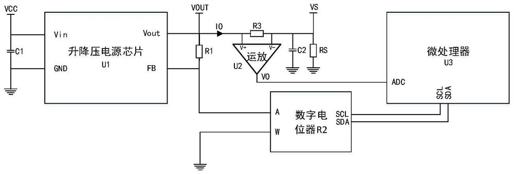
[0036] image 3 It is the circuit diagram of the constant current source of the present invention, which specifically introduces pins such as input Vin, output Vout, feedback FB, and common ground GND of the buck-boost power supply chip U1 in the adjustment circuit, wherein the input Vin pin of the buck-boost power supply chip U1 is connected to the power supply VCC , the output is represented by VOUT, and after passing through the sampling resistor R3, the output voltage is represented by VS, where RS is the load. The control clock pin of the digital potentiometer R2 is SCL, the control data pin is SDA, the control clock terminal SCL of the microprocessor U3 is connected to the control clock terminal SCL of the digital potentiometer R2, and the control data terminal SDA of the microprocessor U3 is connected to the digital The data control terminal SDA of the potentiometer R2, the communication mode adopts I 2 C protocol, the fastest speed can reach 400kHz. The W pin of the ...


PUM


Abstract

The invention discloses a precise constant current source circuit, and belongs to the technical field of radio frequency microwaves. The precise constant current source circuit comprisesa step-up and step-down power supply chip with a step-up and step-down function, a power supply input filter capacitor, a divider resistor, a feedback circuit, a power supply output filter capacitor, a load, a microprocessor internally provided with an ADC module and a digital potentiometer, wherein the feedback circuit comprises a sampling resistor and an operational amplifier. Compared with a traditional constant current source circuit, the precise constant current source circuit is simple in implementation mode, high in current precision and capable of achieving the purpose that the current required by a radio frequency microwave chip jumps rapidly; and meanwhile, output of different currents is controlled through the microprocessor, current limiting value protection is achieved, and the requirement of a more universal constant current source can be met.

Description

technical field [0001] The invention belongs to the technical field of radio frequency microwaves, and in particular relates to a precision constant current source circuit applied in radio frequency microwave control circuits. Background technique [0002] A constant current source refers to a power supply that can provide constant current to different loads, and is a widely used component. figure 1 It is a constant current source circuit in the prior art, including a power MOS transistor Q11, two voltage dividing resistors R11 and R12, two operational amplifiers U11 and U12, a sampling resistor R13 and a voltage source VCC. This circuit is based on a linear power supply through two Two divider resistors R11 and R12 realize the setting of different voltages. The voltage on the sampling resistor R13 is detected by the voltmeter to calculate the current flowing through the load, so as to realize the constant current. This method has problems such as low adjustment efficiency a...

Claims


Application Information

Patent Timeline
IPC IPC(8): G05F1/567
CPCG05F1/567
Inventor 杨青慧刘国超王明肖伟樊鑫安张钰张怀武
Owner UNIV OF ELECTRONIC SCI & TECH OF CHINA
Why Eureka
Try Eureka