Multi-point measurement pneumatic probe based on virtual hole row and application thereof

A multi-point measurement and probe technology, applied in the field of multi-point measurement pneumatic probes based on virtual hole rows, can solve the problem of increased flow field obstruction and disturbance, limited air source capacity, and improve the design of multi-hole pneumatic probes. Problems such as processing difficulty, to achieve the effect of small aerodynamic resistance and flow field disturbance, and low design and processing costs

Active Publication Date: 2021-06-29
中国空气动力研究与发展中心空天技术研究所
View PDF9 Cites 2 Cited by
  • Summary
  • Abstract
  • Description
  • Claims
  • Application Information

AI Technical Summary

Problems solved by technology

To obtain the above aerodynamic parameters, the traditional multi-hole pneumatic probe needs to rely on the displacement mechanism to perform reciprocating scanning measurement in the measurement section, which leads to a sharp increase in the measurement time and increases the operating cost of the wind tunnel, especially for temporary flushing type wind tunnel, due to the limited air source capacity, this measurement scheme is greatly limited
If a multi-point comb-like or rake-shaped porous pneumatic probe is used, the design and processing difficulty of the probe porous pneumatic probe will be increased. At the same time, the increase in the size of the porous pneumatic probe will also increase the aerodynamic force on the probe. Large, and bring problems such as flow field obstruction and disturbance increase

Method used


Image

  • Multi-point measurement pneumatic probe based on virtual hole row and application thereof
  • Multi-point measurement pneumatic probe based on virtual hole row and application thereof

Examples


Embodiment 1

[0036] The multi-point measurement aerodynamic probe based on the virtual hole row in this embodiment is proposed to meet the measurement requirements of the aerodynamic parameters of the cascade outlet section of the impulsive planar cascade wind tunnel.

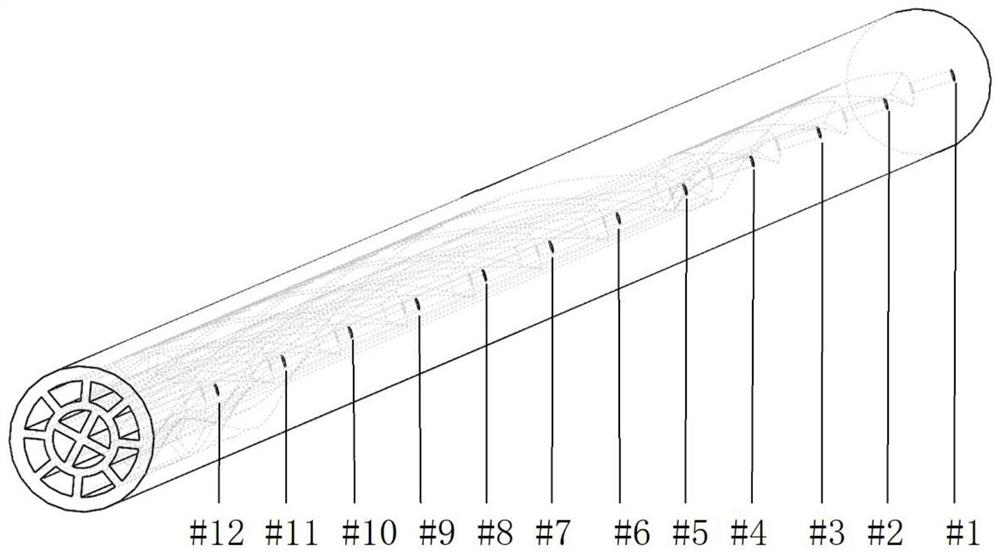
[0037] The internal structure of the multi-point measurement pneumatic probe based on the virtual hole row in this embodiment is complicated, and it is difficult to realize the processing of the internal helix by the traditional processing method, and it needs to be processed and formed by additive manufacturing.

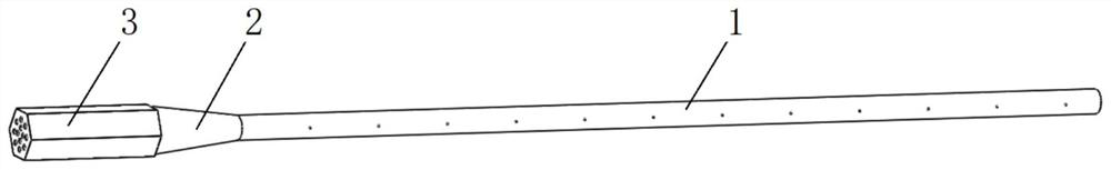
[0038] Such as figure 1 As shown, the multi-point measurement pneumatic probe based on the virtual hole row in this embodiment is composed of a measurement section 1 , a transition section 2 and a clamping section 3 connected in sequence. The probe body is integrally formed by stainless steel additive manufacturing. The measuring section 1 is a cylinder, and the surface roughness is reduced by sandblasting and p...


PUM


Abstract

The invention discloses a multi-point measurement pneumatic probe based on a virtual hole row and application of the multi-point measurement pneumatic probe. The probe sequentially comprises a measuring section, a transition section and a clamping section, the measuring section is a cylindrical section, pressure measuring holes perpendicular to the central axis of the measuring section are formed in the surface of the measuring section, and spiral line or linear pressure guiding pipelines I corresponding to the pressure measuring holes one to one are arranged around the central axis; the transition section is a conical section, and a corresponding pressure guide pipeline II is arranged in the transition section; and the clamping section is a polygon prism section, a corresponding pressure guiding pipeline III is arranged in the clamping section, and the rear end of the clamping section transmits the pressure of the pressure measuring hole to a pressure measuring device through a thin steel pipe and a hose. The probe is low in design and processing cost, small in aerodynamic resistance and flow field disturbance, combined with a displacement mechanism, capable of rapidly achieving atlas measurement of airflow parameters such as the airflow angle, the Mach number, the total pressure and the static pressure of the measured section under the condition of small probe blocking degree, and suitable for rapid measurement of aerodynamic parameters of flow fields such as the temporary impulse type plane cascade wind tunnel cascade outlet section.

Description

technical field [0001] The invention belongs to the technical field of wind tunnel tests, and in particular relates to a multi-point measurement pneumatic probe based on a virtual hole row and an application thereof. Background technique [0002] The calibrated porous pneumatic probe can simultaneously obtain parameters such as flow field total pressure, static pressure, Mach number and flow angle, and is widely used in flow field parameter measurement. For the traditional multi-hole pneumatic probe, to obtain the above aerodynamic parameters, it needs to rely on the displacement mechanism to perform reciprocating scanning measurement in the measurement section, which leads to a sharp increase in measurement time and increases the operating cost of the wind tunnel, especially for temporary impact However, due to the limited air source capacity, this measurement scheme is greatly limited. If a multi-point comb-like or rake-shaped porous pneumatic probe is used, the design an...

Claims


Application Information

Patent Timeline
Patent Type & Authority Applications(China)
IPC IPC(8): G01M9/02G01M9/04
CPCG01M9/02G01M9/04
Inventor 陈峰马护生时培杰任思源李学臣魏巍宗有海黄康
Owner 中国空气动力研究与发展中心空天技术研究所
Why Eureka
Try Eureka