an automatic separation mechanism

An automatic separation and locking mechanism technology, applied in the direction of coupling devices, electrical components, connections, etc., can solve the problems of prolonging the launch time of weapons, and achieve the effects of saving launch time, reducing power supply demand, and saving processing costs

Active Publication Date: 2021-10-01
GUIZHOU SPACE APPLIANCE CO LTD
View PDF6 Cites 0 Cited by
  • Summary
  • Abstract
  • Description
  • Claims
  • Application Information

AI Technical Summary

Problems solved by technology

[0002] The common use mode of the separation connector used in modern airborne weapon systems is: the separation axis of the electrical connector is perpendicular to the course of the projectile, and the electrical connector is a direct plug-in structure, which is locked by an electromagnetic lock on the airborne pylon when in use. The separation mechanism realizes the locking and separation of the electrical connector. For example, the Chinese patent with the publication number CN108258519A provides a planar floating mechanism for separating the connector in the airborne weapon system, which mainly consists of a base, a shell, a guide rod, a guide sleeve, a rotating Cam, locking sleeve, locking end cover, locking spring, locking bushing, locking steel ball, locking ring, floating plate, power spring and other components, is a new type of purely mechanical, touchable The planar floating mechanism solves the problem of mating and locking of the separation connector, but when it is separated, it needs to apply mechanical force to the locking sleeve to push the locking sleeve to unlock. This mode requires the aircraft to provide additional power to the launch system, and "Electrical connector separation" and "weapon launch" must be carried out in sequence, prolonging the time of weapon launch will be a fatal flaw in modern warfare where every second counts

Method used


Image

  • an automatic separation mechanism
  • an automatic separation mechanism
  • an automatic separation mechanism

Examples


Embodiment Construction

[0025] The technical solution of the present invention is further described below, but the scope of protection is not limited to the description.

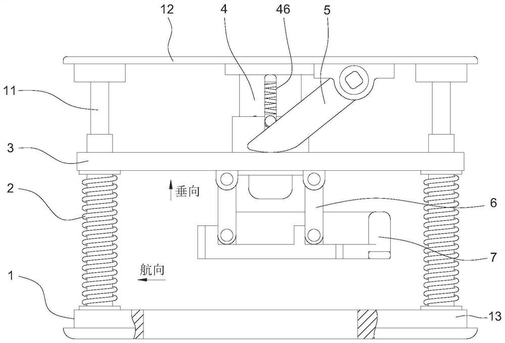
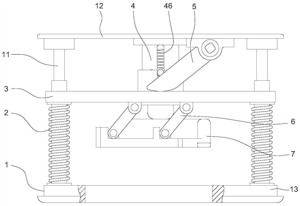
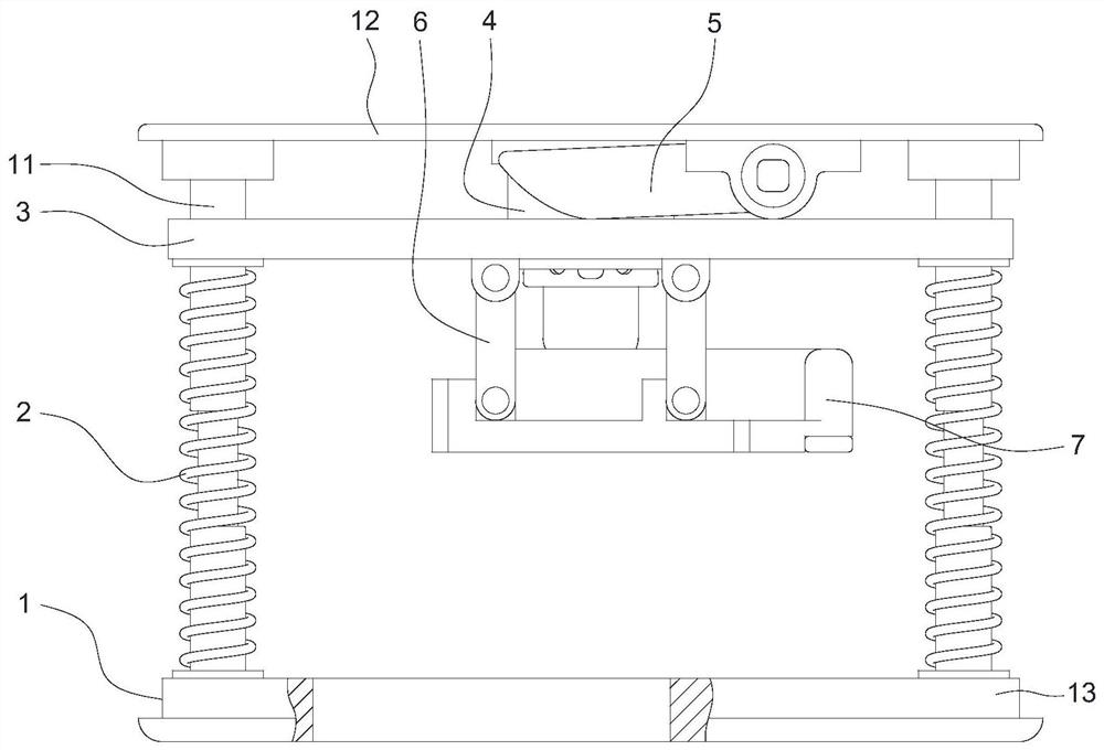
[0026] Such as Figure 1 to Figure 7 As shown, a kind of automatic separation mechanism comprises support 1, floating plate 3, locking mechanism 4 and unlocking mechanism, and support 1 comprises top plate 12 and bottom plate 13, and top plate 12 and bottom plate 13 are fixedly connected by guide rod 11, and the guide rod 11 The axial direction is perpendicular to the course of the projectile body, and the axial direction of the guide rod 11 is generally referred to as the vertical direction in the industry. The floating plate 3 is slipped on the guide rod 11, and the separation spring 2 is set on the guide rod 11, and the separation spring 2 is located on the floating plate. 3 and the bottom plate 13, it is used to push the floating plate 3 to separate the electrical connector mated with the elastic body, one end of the locking me...


PUM


Abstract

The invention provides an automatic separation mechanism, which includes a bracket, a floating plate, a locking mechanism and an unlocking mechanism. The bracket includes a top plate and a bottom plate, and the top plate and the bottom plate are fixedly connected by a guide rod. The plate slides on the guide rod, and the guide rod is equipped with a separation spring. The separation spring is located between the floating plate and the bottom plate. A locking mechanism is fixed on the top plate. One end of the locking mechanism is fixedly connected with the floating plate. Mechanism, the directional movement of the projectile body can push the unlocking mechanism to touch the locking mechanism to unlock, and release the restriction on the movement of the floating plate. The invention provides an automatic separation mechanism, which realizes the launch of the projectile and the separation of the electrical connector at the same time, saves the launch time, and is more suitable for the needs of modern warfare.

Description

technical field [0001] The invention belongs to the technical field of electric connectors, and in particular relates to an automatic separation mechanism, which is used for connection locking, unlocking and separation of electric connectors. Background technique [0002] The common use mode of the separation connector used in modern airborne weapon systems is: the separation axis of the electrical connector is perpendicular to the course of the projectile, and the electrical connector is a direct plug-in structure, which is locked by an electromagnetic lock on the airborne pylon when in use. The separation mechanism realizes the locking and separation of the electrical connector. For example, the Chinese patent with the publication number CN108258519A provides a planar floating mechanism for separating the connector in the airborne weapon system, which mainly consists of a base, a shell, a guide rod, a guide sleeve, a rotating Cam, locking sleeve, locking end cover, locking...

Claims


Application Information

Patent Timeline
Patent Type & Authority Patents(China)
IPC IPC(8): H01R13/629H01R13/639
CPCH01R13/629H01R13/62916H01R13/639
Inventor 肖应富陈谋钦刘贲
Owner GUIZHOU SPACE APPLIANCE CO LTD
Why Eureka
Try Eureka