
Impeller type rotor engine

A rotary engine and impeller-type technology, which is applied in the direction of combustion engines, machines/engines, internal combustion piston engines, etc., can solve the problems of precise manufacturing and rapid development of combustion efficiency constraints, and achieve easy precise machining and grinding, and reduce design and processing costs , the effect of prolonging the service life

Active Publication Date: 2019-06-25
JIANGSU UNIV
View PDF4 Cites 0 Cited by
  • Summary
  • Abstract
  • Description
  • Claims
  • Application Information

AI Technical Summary

Problems solved by technology

However, the precise machining and combustion efficiency of each component of the rotary engine have seriously restricted its rapid development.

Method used


Image

  • Impeller type rotor engine
  • Impeller type rotor engine
  • Impeller type rotor engine

Examples


Embodiment Construction

[0028] The present invention will be further described below in conjunction with the accompanying drawings and specific embodiments, but the protection scope of the present invention is not limited thereto.

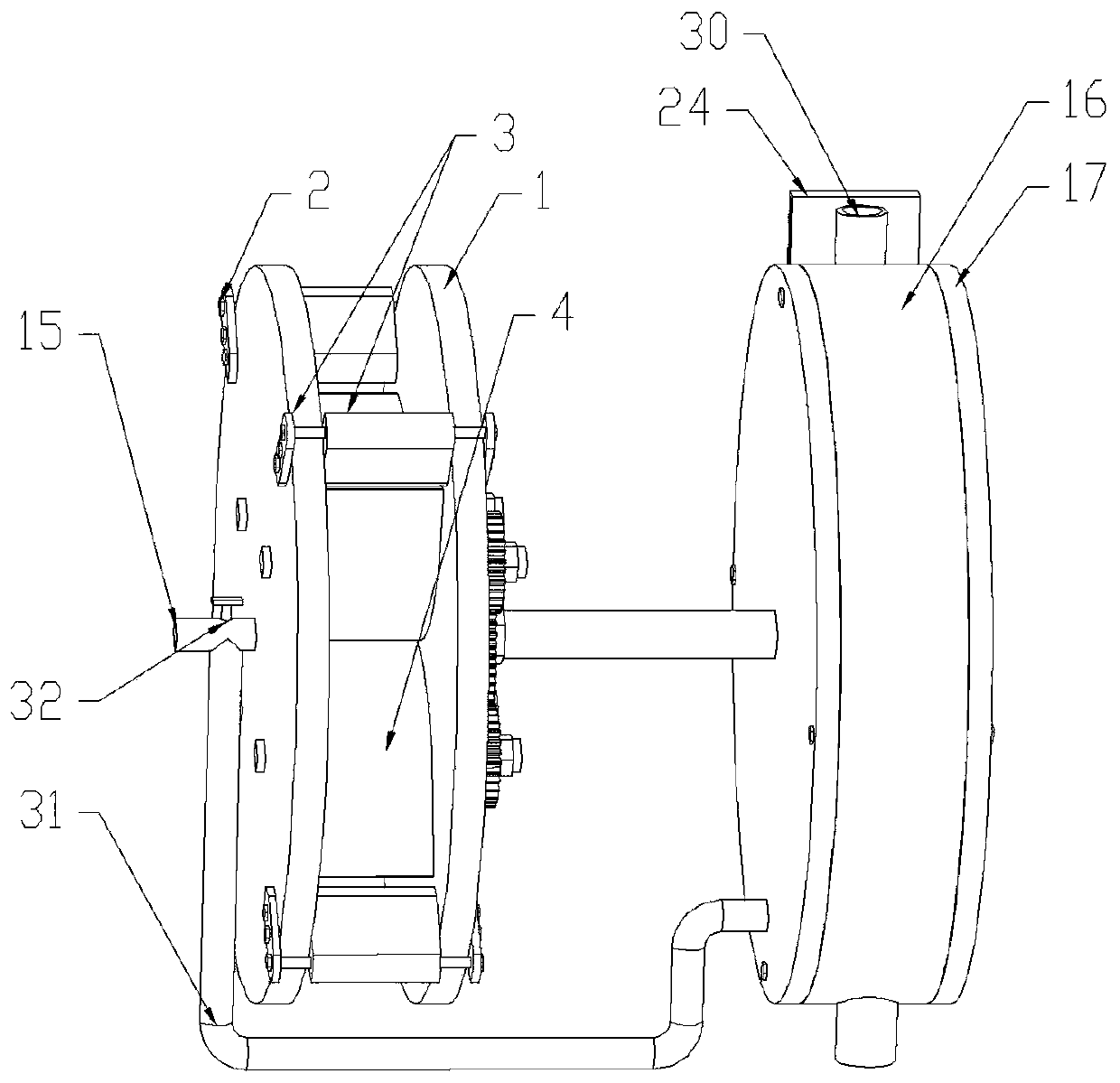
[0029] like figure 1 As shown, the rotary engine described in the present invention includes a first cylinder block and a second cylinder block 16, and the walls of the second cylinder block 16 and the second rotor 18 form several combustion chambers; A rotor compresses and delivers gas to any combustion chamber of the second cylinder 16 to perform work; the second rotor 18 rotates coaxially with the first rotor.

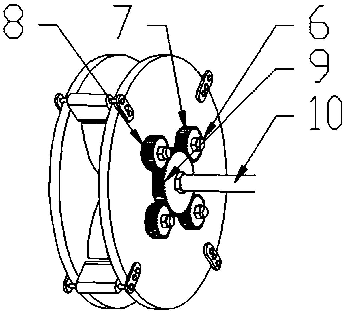
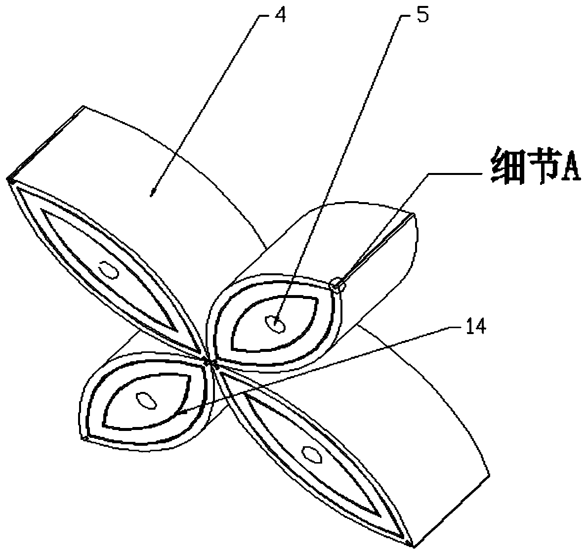
[0030] like figure 2 As shown, two first end covers 1 are fixed on both sides of the first rotor by screws 2 and fixing plates 3 to form a first cylinder body; image 3 As shown, the first rotor includes several impellers 4 and a rotating device, and several of the impellers 4 are evenly distributed in the first cylinder, and the volume of the cavity formed ...


PUM


Abstract

The invention provides a rotor engine. The rotor engine comprises a first cylinder block and a second cylinder block; the wall surface of the second cylinder block and a second rotor form multiple combustion chambers; gas is compressed and conveyed from the internal of the first cylinder block into any combustion chamber of the second cylinder block through a first rotor for acting; and a second rotor and the first rotor are coaxially rotated. The first rotor comprises four impellers and a rotating device; multiple impellers are uniformly distributed in the first cylinder block; through the rotating device, the volume of a cavity formed among the multiple impellers is changed; and in the process of rotating the multiple impellers, at least one end of any impeller is tightly contacted withthe profiles of the adjacent impellers. The impeller type rotor engine can realize the intake compression and combustion exhaust process thereof in different cylinder blocks, so that the performancesof the rotor engine are improved.

Description

technical field [0001] The invention relates to the technical field of rotary engines, in particular to an impeller-type rotary engine. Background technique [0002] The rotary engine is another high-efficiency power machine besides the traditional reciprocating engine. It is widely used in many civil and military fields due to its advantages such as fewer parts and smooth operation. Especially in recent years, the rapid development of electric vehicles and small unmanned aerial vehicles has brought new opportunities to the development of rotary engines, because the range extender and small unmanned aerial vehicles, which are the core components of extended-range electric vehicles, are in urgent need of a A power plant with compact structure and high power-to-weight ratio, and the unique advantages of the rotary engine make it just meet the requirements of this pair of power plants. However, the precise machining and combustion efficiency of each component of the rotary eng...

Claims


Application Information

Patent Timeline
Patent Type & Authority Applications(China)
IPC IPC(8): F02B55/02F02B55/08
Inventor 范宝伟王远光张耀元潘剑锋陈伟陆尧
Owner JIANGSU UNIV
Learn More