A microchannel plate fixing device

A technology of micro-channel plate and fixing device, which is applied in the field of photoelectric detection, can solve the problems of slight damage on the surface of the device, high pressure of the micro-channel plate, and high pressure of the trapezoidal spring pressure ring, etc., to achieve the quantification of the clamping program, expand the application occasions, even force effect

Active Publication Date: 2022-05-27
CHANGCHUN INST OF OPTICS FINE MECHANICS & PHYSICS CHINESE ACAD OF SCI
View PDF9 Cites 0 Cited by
  • Summary
  • Abstract
  • Description
  • Claims
  • Application Information

AI Technical Summary

Problems solved by technology

Detectors based on microchannel plates work under negative high voltage conditions, and slight damage to the surface of the device may cause high-voltage discharges, making the detector unusable
[0003] The existing micro-channel plate fixing device generally uses elastic elements to fix the micro-channel plate. The patent application number is 201720100511. The pressure generated by the pressure ring is reduced, which improves the yield to a certain extent, but does not fundamentally solve the problem of micro-channel plate assembly
[0004] The patent with the application number 201610335825.8 and the patent with the application number 201610335825.8 use springs and buffer blocks to fix the micro-channel plate. Although the problem of shock absorption is considered, there are problems such as uneven force on the device, and the local pressure of the micro-channel plate may be too large
The use of rubber cannot be used in sealed detectors, which limits the application of micro-channel plates
[0005] The patent application number is 201810092982.X. The micro-channel plate and the collector are fixed by placing a spring in the middle of the back. The mechanical requirements of the components limit the application of microchannel plates
[0006] The application number is 201020634403.9. Rubber is used for shock absorption. The problem of rubber outgassing affects the vacuum degree, which limits the use of micro-channel plates.

Method used


Image

  • A microchannel plate fixing device
  • A microchannel plate fixing device
  • A microchannel plate fixing device

Examples


Embodiment 1

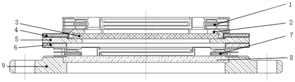
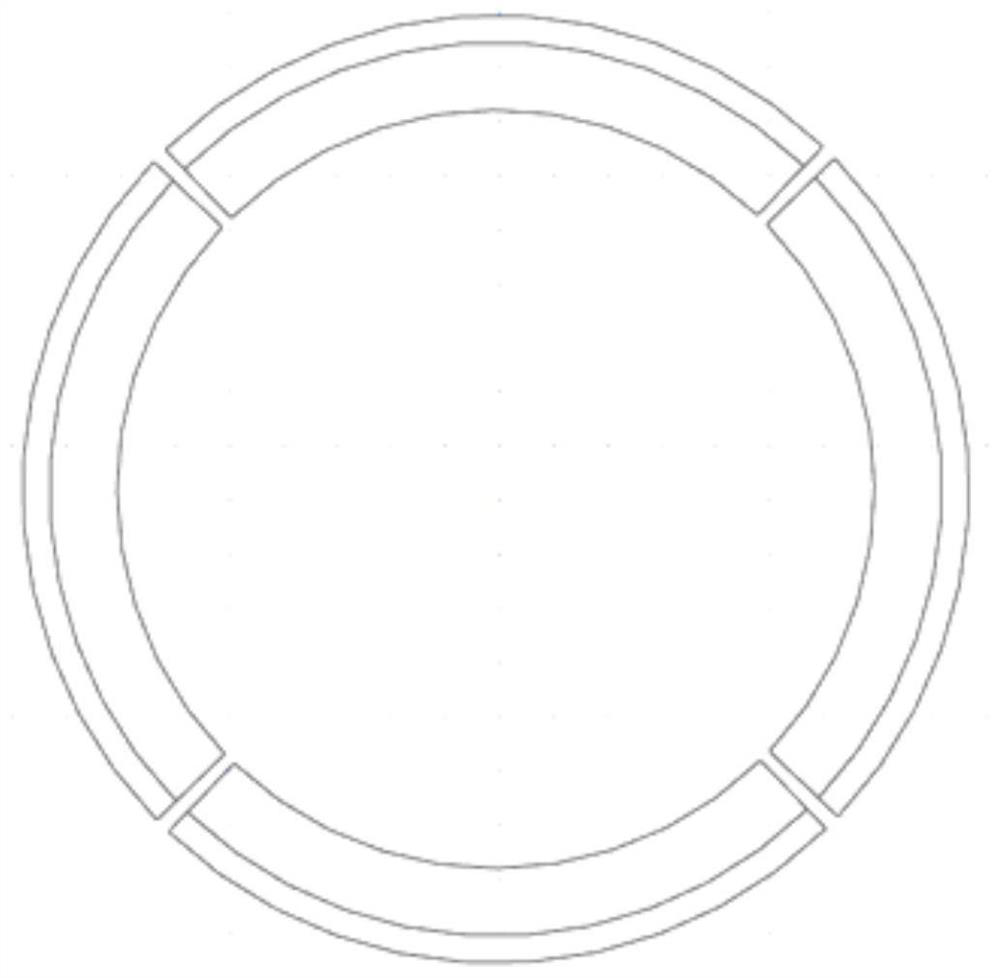
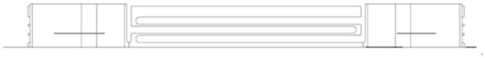
[0031] Please refer to figure 1 , a microchannel plate fixing device provided in the embodiment of the present application includes a ring-shaped base 9, a collector electrode 8, a second elastic pressing ring 7, an insulating plate 6, a microchannel plate base stacked on the base 9 in sequence 5. Insulation positioning ring 4, micro-channel plate 3, arc-shaped positioning ring 2, first elastic pressure ring 1, this embodiment fixes a micro-channel plate, by adjusting the mechanical size, the micro-channel plate base 5 and the first elastic pressure ring 1-3 microchannel plates can be placed between 1.

[0032] The upper surface of the base 9 is provided with a first groove, and the collector 8 is arranged in the first groove, and the collector 8 is used to receive the electron flow multiplied by the microchannel plate 3 .

[0033] The second elastic pressure ring 7 is arranged on the collector 8, the second elastic pressure ring 7 and the base 9 clamp the collector, and the ...


PUM


Abstract

The application provides a microchannel plate fixing device, which includes an annular base, a collector stacked on the base, a second elastic pressure ring, an insulating plate, a microchannel plate base, an insulating positioning ring, a microchannel plate, The arc positioning ring, the first elastic pressure ring, the second elastic pressure ring and the base clamp the collector to realize the positioning of the upper surface, side surface and lower surface of the collector; the arc positioning The ring, the insulating positioning ring and the micro-channel plate base clamp the micro-channel plate to realize the positioning of the upper surface, the side surface and the lower surface of the micro-channel plate. A fixing device for a microchannel channel plate of the present application can perform shock absorption and fixation on the microchannel plate to ensure that the two sides of the microchannel plate are evenly stressed, and the elastic pressure ring has a certain elastic buffer capacity. Accurate control of the pressing force required for fixing the microchannel plate can be achieved.

Description

technical field [0001] The present application relates to the field of photoelectric detection, and more particularly, to a microchannel plate fixing device. Background technique [0002] A microchannel plate is a channel array composed of several millions or even tens of millions of parallel arranged 4-12μm channel apertures and 6-15μm hole spacing glass channels, and then beveled at a certain angle to form a thickness. The glass flakes of the order of 0.25-0.80 mm are coated with conductive films on both sides of the microchannel plate, and the porous structure is extremely fragile. Detectors based on microchannel plates work under negative high voltage conditions, and slight damage to the surface of the device may cause high voltage discharge, making the detector unusable. [0003] The existing microchannel plate fixing device generally adopts elastic elements to fix the microchannel plate. The patent application number is 201720100511.X. Although the L-shaped spring pre...

Claims


Application Information

Patent Timeline
Patent Type & Authority Patents(China)
IPC IPC(8): B25B11/02
CPCB25B11/02
Inventor 张宏吉郭权锋陈波刘阳
Owner CHANGCHUN INST OF OPTICS FINE MECHANICS & PHYSICS CHINESE ACAD OF SCI
Why Eureka
Try Eureka