
Method and system for estimating disturbance torque caused by asymmetric rotational scanning load

A technology of rotating scanning and interfering torque, applied in the aerospace field, can solve problems such as affecting the accuracy of load attitude control

Active Publication Date: 2021-06-25
BEIJING INST OF CONTROL ENG
View PDF6 Cites 2 Cited by
  • Summary
  • Abstract
  • Description
  • Claims
  • Application Information

AI Technical Summary

Problems solved by technology

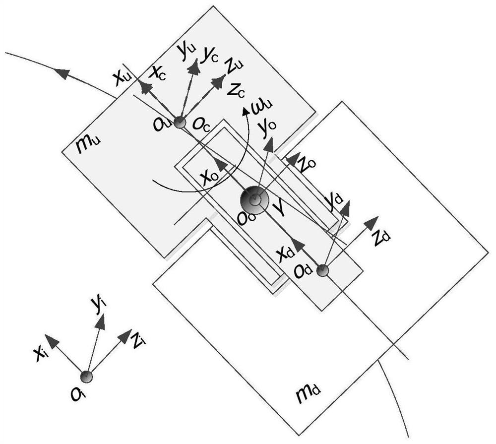
[0006] In view of the fact that the rotating scanning satellite is a multi-body structure composed of a load cabin and a platform cabin, the dynamics between them are coupled through the magnetic suspension bearing in the middle; while the moment of inertia and angular momentum of the load cabin undergoing complex rotation on the orbital plane are the same as The directions are all nonlinear functions of the attitude, and they are coupled with the angular velocity, so that the load compartment will be subjected to the reaction moment of variable inertia, the gyro moment generated by the action of angular momentum and angular velocity, and the unbalanced moment caused by the deflection of the rotation axis and the main inertia axis, There is also the bias current torque generated by the camera beam splitter, etc. Obviously, the first three items are mainly due to the rotation of the load compartment, which affects the attitude control accuracy of the payload in the satellite.

Method used


Image

  • Method and system for estimating disturbance torque caused by asymmetric rotational scanning load
  • Method and system for estimating disturbance torque caused by asymmetric rotational scanning load
  • Method and system for estimating disturbance torque caused by asymmetric rotational scanning load

Examples


Embodiment

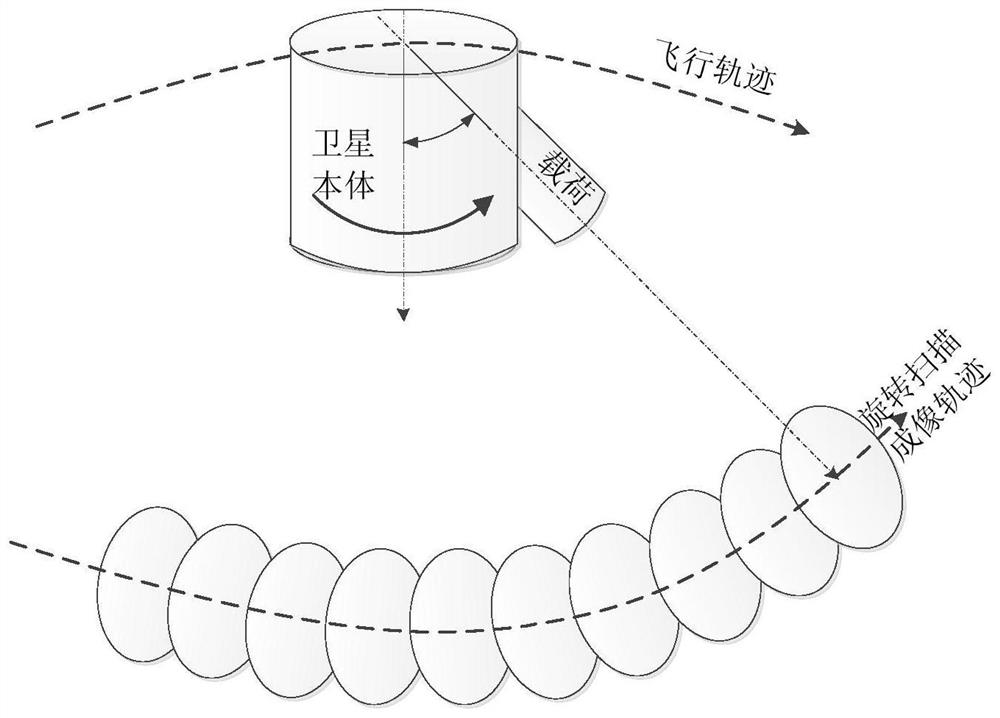
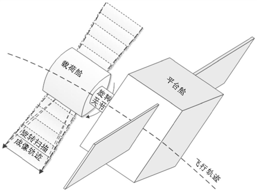
[0121] The rotational scanning imaging of the load compartment mainly includes conical scanning ( figure 2 ), vertical orbit scan and along-orbit scan (spinning satellite scan) and other modes. The present invention sweeps with the vertical rail ( image 3 shown) as an example to perform interference analysis and calculation.

[0122] The load cabin rotates around the x-axis of the flight direction, then the rotation matrix from the local system to the orbital system to the inertial system is:

[0123]

[0124] Among them, ω ux0 is the angular velocity of the load compartment rotating around its x-axis; ω uy0 is the rotational angular velocity of the star around the y-axis; ω uz0 = 0 means no rotation of the load compartment about the z-axis; they are the nominal angular velocities of the load compartment relative to the inertial frame. ie [ω ux0 ω uy0 ω uz0 ] T =[ω ux0 ω uy0 0] T ;and

[0125] Since the attitude control is carried out in the orbit system,...


PUM


Abstract

The invention discloses a method and a system for estimating disturbance torque caused by an asymmetric rotational scanning load. The method comprises the following steps of: calculating according to coordinate conversion to obtain a rotational inertia matrix of a rotating body formed by a load cabin and a magnetic suspension joint rotor in an orbital coordinate system; calculating to obtain the angular velocity vector of the rotating body in the inertial coordinate system; calculating the angular momentum of the load cabin according to the rotational inertia matrix and the angular velocity vector of the rotating body; establishing the attitude dynamic model of the rotating body according to an Euler equation; classifying nominal rotating speeds in the attitude dynamical model to obtain a variable inertia reaction torque and gyroscopic torque interference model caused by an orbital angular velocity and a rotating body angular velocity; and substituting the rotational inertia of the rotating body in the satellite and the nominal rotating speed of the rotating body into the interference model, and estimating constant value, first frequency multiplication and second frequency multiplication interference torques caused by the rotating body. According to the invention, a basis for applying interference is provided for control, ground simulation and test verification of the magnetic suspension rotary joint and the satellite.

Description

technical field [0001] The invention relates to a method and system for estimating disturbance moment, belonging to the field of aerospace technology. Background technique [0002] Magnetic suspension bearing is a high-performance bearing that uses magnetic field force to levitate the rotor. Since the magnetic suspension bearing has many advantages such as no friction, no wear, no lubrication, low cost, low loss, long life, etc., it can be used in a wide range of application fields such as high-speed motion occasions and low-speed motion occasions. [0003] The rotating scanning satellite realizes the intersection of the scanning trajectory and the flight trajectory through the steady rotation of the payload (such as a camera, etc.), such as pendulum scanning, cone scanning, and ring scanning, thereby significantly expanding the scanning range of the payload. In the modes of fast scanning imaging or splicing imaging of the camera and other loads, ultra-wide imaging at the l...

Claims


Application Information

Patent Timeline
Patent Type & Authority Applications(China)
IPC IPC(8): G05D17/02
CPCG05D17/02Y02T90/00
Inventor 罗睿智张激扬樊亚洪武登云张鹏波王英广王舒雁齐明杨磊姚锐李建普顾正成肖晓张春艳刘建冯洪伟赵严杜金龙
Owner BEIJING INST OF CONTROL ENG
Learn More