
Non-contact voltage sensor

A voltage sensor, non-contact technology, applied in the direction of measuring only voltage, measuring current/voltage, phase angle between voltage and current, etc., can solve problems such as single function and error, achieve frequency bandwidth, high precision, structure simple effect

Active Publication Date: 2021-06-25
珠海多创科技有限公司
View PDF12 Cites 6 Cited by
  • Summary
  • Abstract
  • Description
  • Claims
  • Application Information

AI Technical Summary

Problems solved by technology

In the field of low-voltage measurement, the voltage measurement device is usually contact measurement. In the field of high-voltage measurement, the voltage measurement device includes voltage transformers and capacitive voltage sensors. Voltage transformers can realize the monitoring of electrical equipment and key nodes inside substations and converter stations Real-time sensing and measurement, but its single function can only be used to measure power frequency voltage signals
The capacitive voltage sensor uses the sensing electrode and the measured conductor to form a coupling capacitance, which can collect the AC voltage signal on the measured conductor, but can only collect the frequency information of the measured AC voltage signal. In the case of uncalibrated, The amplitude information of the measured AC voltage cannot be directly obtained, and in the voltage detection scene, the spatial coupling capacitance formed between the sensing electrode and the measured conductor will also change with changes in air humidity, insulating material aging, and relative spatial position , the voltage amplitude information collected after calibration will also have a huge error due to the above factors

Method used


Image

  • Non-contact voltage sensor
  • Non-contact voltage sensor
  • Non-contact voltage sensor

Examples


Embodiment 1

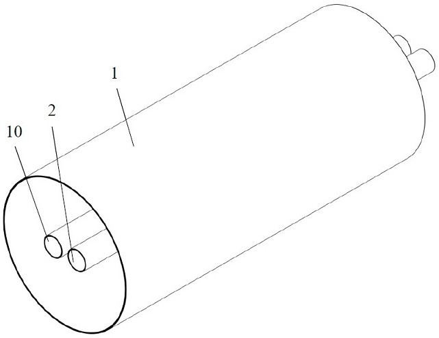
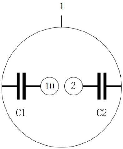
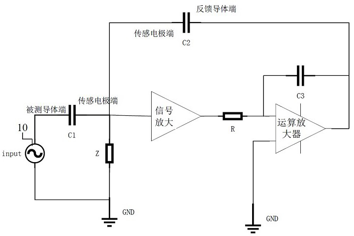
[0024] refer to figure 1 , figure 2 and image 3 , the voltage sensor of this embodiment includes a sensing electrode 1, a feedback conductor 2 and a signal amplification module. The sensing electrode 1 is made of conductive materials such as metal and semiconductor, and the measured conductor 10 and the feedback conductor 2 both pass through the non-enclosed space formed by the sensing electrode 1 . Such as figure 1 and figure 2 As shown, the sensing electrode 1 of this embodiment is hollow cylindrical, and the measured conductor 10 passes through the sensing electrode 1, and can form a coupling capacitance with the sensing electrode 1, and the measured conductor 10 and the sensing electrode The coupling capacitance formed between 1 is defined as the input coupling capacitance C1, and the voltage signal on the conductor 10 under test is collected through the input coupling capacitance. The feedback conductor 2 also passes through the sensing electrode 1, and it is spac...

Embodiment 2

[0030] Such as Figure 6 As shown, the difference between this embodiment and Embodiment 1 is that: multiple feedback conductors (2_(1), 2_(2), ..., 2_(n)) are set in the sensing electrode 1, and multiple feedback conductors and the measured conductor 10 are evenly spaced along the circumferential direction, the positions of the measured conductor and each feedback conductor are rotationally symmetrical, and feedback coupling capacitance is formed between each feedback conductor and the sensing electrode 1 . Each feedback conductor is a conductor of the same shape made of the same material as the measured conductor, and each feedback conductor is connected to the output terminal of the signal amplification module. At this time, the feedback coupling capacitance is n times the input coupling capacitance (nC1≈ C2, that is, C2: C1 = n: 1, similarly, the difference between nC1 and C2 is considered to be approximately equal if the difference is within 10%, n is the number of feedba...


PUM


Abstract

A non-contact voltage sensor comprises: a sensing electrode, the sensing electrode is provided with a space for a measured conductor to pass through, an input coupling capacitor is formed between the measured conductor and the sensing electrode, and grounding impedance is formed between the sensing electrode and the ground; at least one feedback conductor which penetrates through the sensing electrode, wherein a feedback coupling capacitor is formed between the feedback conductor and the sensing electrode, and the feedback coupling capacitor is proportional to the input coupling capacitor; a signal amplification module, wherein the output end of the sensing electrode is connected with the input end of the signal amplification module, the output end of the signal amplification module is connected with the feedback conductor, the signal amplification module outputs a voltage measurement result, and the signal amplification module is used for amplifying an alternating current voltage signal sensed by the sensing electrode and performing phase shift on the voltage signal, the amplitude of the voltage output by the signal amplification module and the amplitude of the to-be-measured voltage form a linear relation, and the phase of the voltage is opposite to the phase of the to-be-measured voltage. According to the invention, a closed-loop sensing principle is adopted, and non-contact measurement of amplitude, phase and frequency of alternating voltage can be realized.

Description

technical field [0001] The invention belongs to the technical field of power sensing, and in particular relates to a non-contact voltage sensor. Background technique [0002] Voltage is one of the most basic signals in electronic systems, and the application of voltage measurement devices is ubiquitous in power systems. In the field of power sensing, the acquisition of AC voltage signals and the measurement of AC voltage amplitude are very important. In the field of low-voltage measurement, the voltage measurement device is usually contact measurement. In the field of high-voltage measurement, the voltage measurement device includes voltage transformers and capacitive voltage sensors. Voltage transformers can realize the monitoring of electrical equipment and key nodes inside substations and converter stations Real-time sensing and measurement, but its single function can only be used to measure power frequency voltage signals. The capacitive voltage sensor uses the sensin...

Claims


Application Information

Patent Timeline
Patent Type & Authority Applications(China)
IPC IPC(8): G01R19/00G01R19/04G01R25/00G01R23/02
CPCG01R19/0084G01R19/04G01R23/02G01R25/00
Inventor 刘明胡忠强毛若浩关蒙萌刘佳明
Owner 珠海多创科技有限公司
Learn More