A thermal induction self-lubricating bearing wear-resistant bushing

A self-lubricating, thermal induction technology, applied in the direction of sliding contact bearings, rotating bearings, bearings, etc., can solve the problems of inconvenient operation, refueling, pertinence and poor flexibility, and achieve easy embedded installation and reduced friction Effect

Active Publication Date: 2022-06-24
南通通途机电制造有限公司
View PDF5 Cites 0 Cited by
  • Summary
  • Abstract
  • Description
  • Claims
  • Application Information

AI Technical Summary

Problems solved by technology

In the prior art, manual oiling is usually required, and it is difficult to oil the oil according to the friction between the bearing and the bushing, the operation is inconvenient, and the pertinence and flexibility are poor

Method used


Image

  • A thermal induction self-lubricating bearing wear-resistant bushing
  • A thermal induction self-lubricating bearing wear-resistant bushing
  • A thermal induction self-lubricating bearing wear-resistant bushing

Examples


Embodiment 1

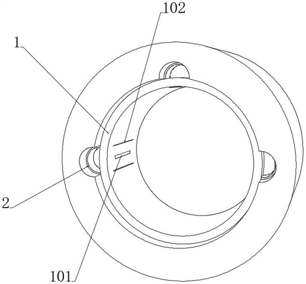
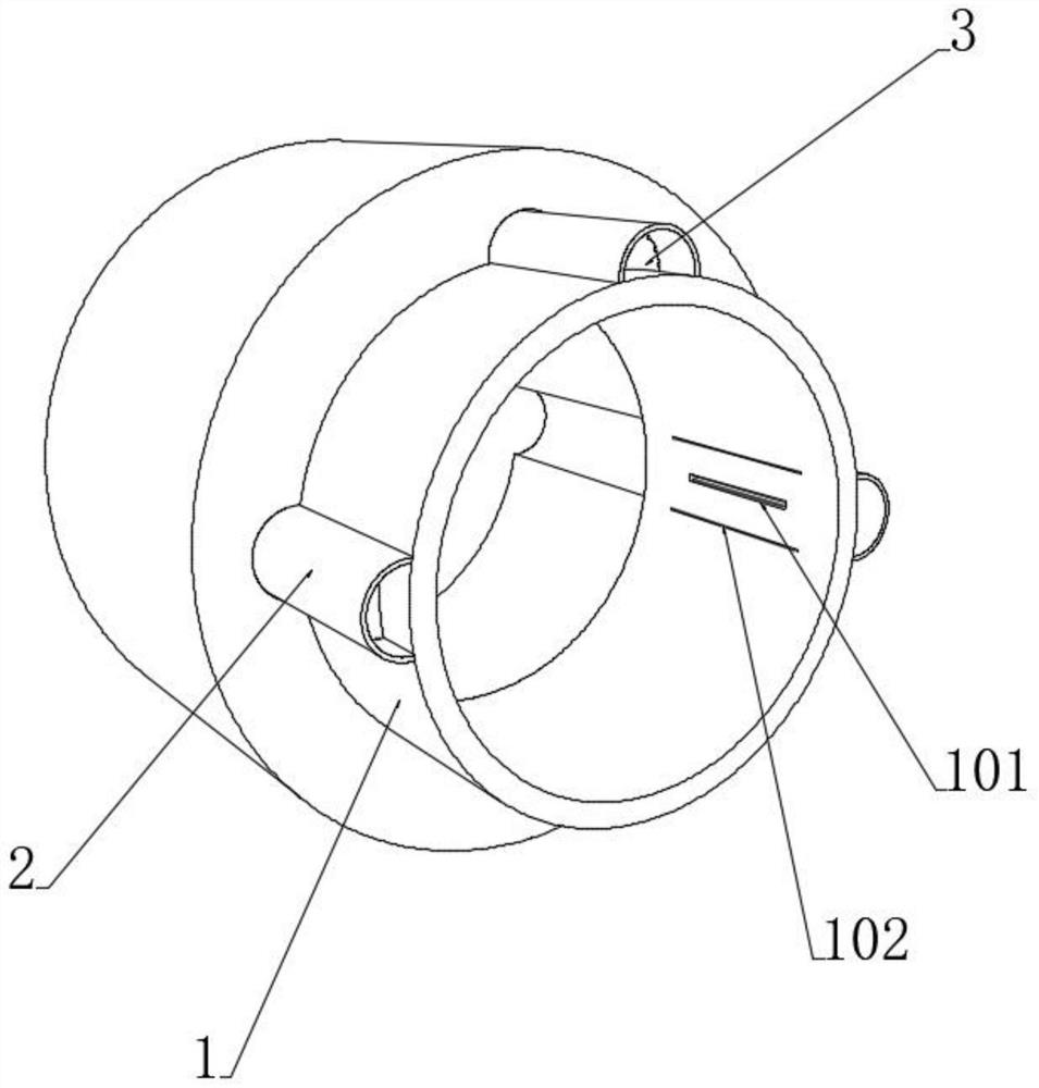
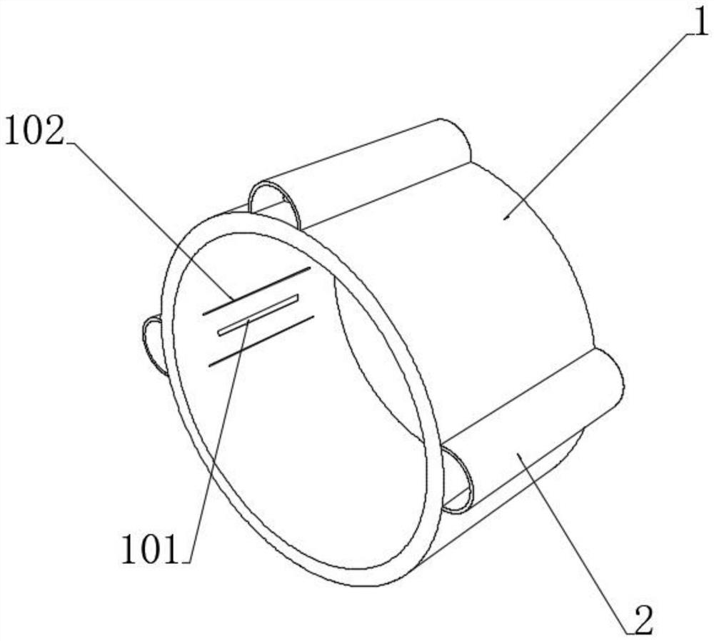
[0045] see Figure 1-3 and Figure 6-7 , a heat-induced self-lubricating bearing wear-resistant shaft sleeve, comprising a sleeve body 1, the sleeve body 1 is sleeved in the shaft sleeve hole, the top and both sides of the outer side wall of the sleeve body 1 are fixedly connected with an embedded sleeve 2, the shaft An embedding cavity corresponding to the position of the embedding sleeve 2 is opened in the sleeve hole, and an oil feed body is sleeved and installed in the interior of the plurality of embedded sleeves 2. The inner wall of the sleeve body 1 is provided with a corresponding position of the oil feed body. The oil outlet 101, the oil supply body includes a heat conduction sleeve 3 embedded in the inner side of the embedded sleeve 2, the inner middle of the heat conduction sleeve 3 is provided with an oil storage bag 4, and the upper and lower ends of the heat conduction sleeve 3 are filled with the upper and lower ends of the oil storage bag 4. The thermal expans...


PUM


Abstract

The invention discloses a heat-induced self-lubricating bearing wear-resistant shaft sleeve, which belongs to the technical field of wear-resistant shaft sleeves. Set the sleeve, the embedded sleeve and the shaft sleeve hole are embedded and matched with each other, which is easy to install the sleeve body stably. There is an oil storage bag filled with lubricating oil inside the heat transfer sleeve, and the upper and lower sides of the heat transfer sleeve are equipped with oil storage bags. The closely attached thermal expansion packing layer, after the bearing and the shaft sleeve rub against each other to generate heat, the heat is transferred to the heat conduction sleeve through the heat conductor connected between the sleeve body and the embedded sleeve, as the thermal expansion condition of the thermal expansion packing layer, a After the heat-expandable packing layer is thermally expanded, the oil storage bag can be squeezed in two directions, so that the lubricating oil inside the oil storage bag can overflow to the oil outlet groove through the oil outlet pipe, and oil can be supplied to the bearing in the casing, which is targeted and flexible Oil supply operation without manual operation.

Description

technical field [0001] The invention relates to the technical field of wear-resistant shaft sleeves, and more particularly, to a heat-induced self-lubricating bearing wear-resistant shaft sleeve. Background technique [0002] In the moving parts, the rotating shaft is installed in the shaft hole, because long-term use will cause wear between the rotating shaft and the shaft hole, usually the shaft sleeve is arranged on the rotating shaft to protect the rotating shaft. [0003] However, the rotating shaft and the shaft sleeve are constantly rubbing during the matched use process. Once the friction is excessive, it will not only cause the wear of the end face of the rotating shaft and affect the service life, but also cause the temperature between the rotating shaft and the shaft sleeve due to long-term friction. It is not easy for the bearing to work for a long time in a high temperature environment. [0004] At present, lubricating oil is added between the shaft sleeve and ...

Claims


Application Information

Patent Timeline
Patent Type & Authority Patents(China)
IPC IPC(8): F16C17/12F16C33/04F16N1/00
CPCF16C17/12F16C33/04F16N1/00
Inventor 顾斌
Owner 南通通途机电制造有限公司
Why Eureka
Try Eureka