Floating type brick body heat insulation structure

A floating, brick-body technology, applied in building structures, building materials, buildings, etc., can solve the problems of unadjustable thickness, restricted use range, adjustment, etc., to increase the air insulation interval, adjustable thermal insulation effect, The effect of driving convenience

Inactive Publication Date: 2021-06-25
港泰耐火材料(江苏)有限公司
View PDF0 Cites 0 Cited by
  • Summary
  • Abstract
  • Description
  • Claims
  • Application Information

AI Technical Summary

Problems solved by technology

[0002] Heat insulation bricks have the function of heat insulation, and are mainly used for heat insulation and heat preservation projects of building sky, inner and outer walls, slope top building foundation and inner and outer roofs; heat insulation bricks include inner layer and outer layer wrapping inner layer, traditional insulation The outer layer of the thermal brick is generally wrapped with cement mortar to wrap the inner layer of the thermal insulation brick. The existing cement mortar outer layer and the inner layer of the thermal insulation brick are generally fixed and bonded together, so that the thermal insulation brick is an integral structure, and In different places of use and the degree of heat insulation required, the thickness of the existing heat insulation bricks is generally unable to be adjusted, so that the thickness of the stack cannot be adjusted, and the existing heat insulation bricks are all produced in a complete set. It is greatly restricted. In addition, when it is necessary to improve the heat insulation effect, the existing heat insulation bricks cannot be flexibly adjusted.

Method used


Image

  • Floating type brick body heat insulation structure
  • Floating type brick body heat insulation structure
  • Floating type brick body heat insulation structure

Examples


Embodiment Construction

[0019] The content of the present invention will be further described in detail below in conjunction with the accompanying drawings.

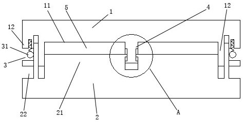
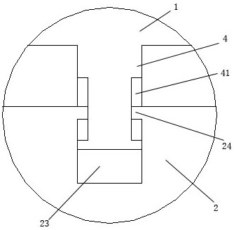
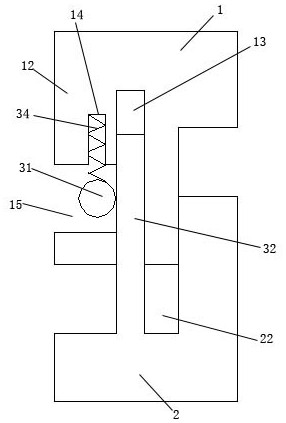
[0020] Such as Figures 1 to 4 As shown, a floating brick heat insulation structure includes an external decorative board 1, an internal heat insulating board 2, and a floating assembly 3; the inner surface of the external decorative board 1 is provided with a plugging groove 11; the plugging An annular protrusion 12 is provided around the groove 11; an insertion projection 21 is provided on the outside of the internal heat insulation board 2; an annular groove 22 is provided around the insertion projection 21; The plate 2 is slidably inserted into the insertion groove 11 in the middle of the inner surface of the outer decorative panel 1 through the insertion protrusion 21 in the middle; the annular protrusion 12 of the outer decorative panel 1 is inserted and connected to the annular In the groove 22; a floating assembly 3 is installed on bot...


PUM


Abstract

The invention discloses a floating type brick body heat insulation structure. The heat insulation structure comprises an external decorative plate, an internal heat insulation plate and a floating assembly. The heat insulation structure is characterized in that an integrated structure of a traditional heat insulation brick is changed into a mounting structure with the internal heat insulation plate floating on the inner side of the external decorative plate; a driving gear is rotated to drive a floating plate to float up and down, so as to drive the internal heat insulation plate to float up and down, such that a thickness of the entire heat insulation brick is adjusted; in addition, if a heat insulation effect of the heat insulation brick needs to be improved, the internal heat insulation plate can be adjusted to be far away from the external decorative plate, so that the thickness of a heat insulation adjusting gap between an insertion lug on the outer side of the internal heat insulation plate and an insertion groove in the inner side face of the external decorative plate is increased, and an air heat insulation space is increased. The heat insulation structure is flexible to use and adjustable in heat insulation effect.

Description

technical field [0001] The invention relates to a floating brick heat insulation structure. Background technique [0002] Heat insulation bricks have the function of heat insulation, and are mainly used for heat insulation and heat preservation projects of building sky, inner and outer walls, slope top building foundation and inner and outer roofs; heat insulation bricks include inner layer and outer layer wrapping inner layer, traditional insulation The outer layer of the thermal brick is generally wrapped with cement mortar to wrap the inner layer of the thermal insulation brick. The existing cement mortar outer layer and the inner layer of the thermal insulation brick are generally fixed and bonded together, so that the thermal insulation brick is an integral structure, and In different places of use and the degree of heat insulation required, the thickness of the existing heat insulation bricks is generally unable to be adjusted, so that the thickness of the stack cannot...

Claims


Application Information

Patent Timeline
Patent Type & Authority Applications(China)
IPC IPC(8): E04C1/41E04B1/38
CPCE04B1/38E04C1/41
Inventor 樊秋官
Owner 港泰耐火材料(江苏)有限公司
Why Eureka
Try Eureka