
Ejection device of injection mold

A technology for injection molds and ejection devices, which is applied in the field of injection mold ejection devices, can solve the problems of lower production efficiency, long time, labor and labor, etc., and achieve the effects of improving work efficiency, accelerating cooling and molding, and saving labor

Inactive Publication Date: 2021-06-25
高春鹏
View PDF5 Cites 2 Cited by
  • Summary
  • Abstract
  • Description
  • Claims
  • Application Information

AI Technical Summary

Problems solved by technology

[0003] However, in the current injection molding production process, in each cycle of injection molding, the plastic part must be taken out of the mold cavity, and the mechanism that completes the action of taking out the plastic part is the ejection mechanism. Most of the existing technologies use a driving device Drive the ejector rod to push the mold out of the mold cavity, and then manually open the mold. After the mold is opened, the workpiece must be taken out manually. The operation process is cumbersome, which reduces the production efficiency. , the ejector device is often only able to eject a part of the molding material product, and it is necessary to manually take the molding material product out of the mold, which is laborious. The process in the area generally takes a long time, which greatly reduces the continuous production efficiency of the enterprise, so an injection mold ejection device is urgently needed to solve the problem

Method used


Image

  • Ejection device of injection mold
  • Ejection device of injection mold
  • Ejection device of injection mold

Examples


Embodiment Construction

[0022] The following will clearly and completely describe the technical solutions in the embodiments of the present invention with reference to the accompanying drawings in the embodiments of the present invention. Obviously, the described embodiments are only some, not all, embodiments of the present invention.

[0023] In describing the present invention, it should be understood that the terms "upper", "lower", "front", "rear", "left", "right", "top", "bottom", "inner", " The orientation or positional relationship indicated by "outside", etc. is based on the orientation or positional relationship shown in the drawings, and is only for the convenience of describing the present invention and simplifying the description, rather than indicating or implying that the referred device or element must have a specific orientation, so as to Specific orientation configurations and operations, therefore, are not to be construed as limitations on the invention.

[0024] refer to Figure ...


PUM


Abstract

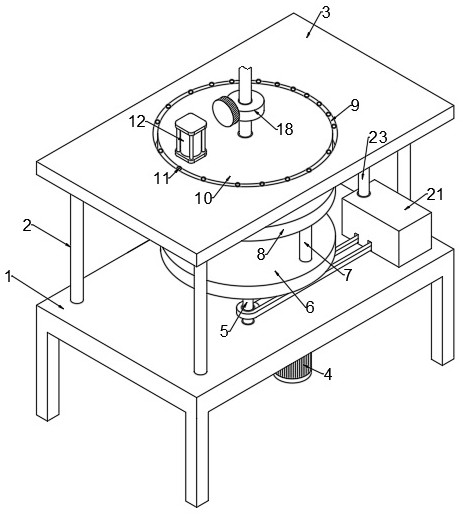
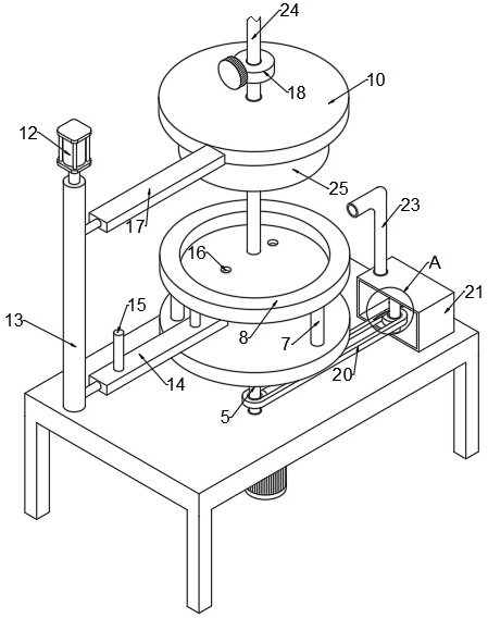
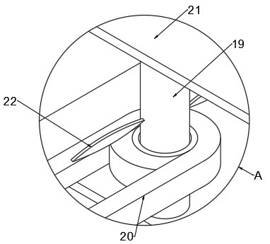
The invention discloses an ejection device of an injection mold. The ejection device of the injection mold comprises a workbench, wherein supporting legs are fixedly connected to the four opposite angles of the workbench, the tops of the four supporting legs are fixedly connected with the same top plate, a driving motor is fixedly connected to the bottom of the workbench, the output end of the driving motor is fixedly connected with a driving shaft, and the driving shaft penetrates through the workbench and is fixedly connected with a bottom plate. Through cooperative use of the driving motor, the driving shaft, a floor, supporting rods, a bottom mold, a mounting opening, a rotating plate, an air cylinder, a telescopic rod, a fixing plate, an ejector pin, an ejector opening and a connecting plate, injection molding materials can be evenly fed, and then materials can be evenly stored in the bottom mold; and meanwhile through cooperative use of the air cylinder, the telescopic rod, the connecting plate and the fixing plate, rapid and automatic ejection of the injection mold is achieved, the problem that in a traditional device, demolding of an injection mold is achieved in a manual ejection mode is solved, and labor is saved.

Description

technical field [0001] The invention relates to the technical field of mold ejection, in particular to an injection mold ejection device. Background technique [0002] In the injection molding process, the product is cooled and formed in the mold. Due to the volume shrinkage of the product, a tight force is generated on the core. In each cycle of injection molding, the tight force and the friction force must be overcome, and the pressure holding is over. Finally, the cooled and solidified plastic parts and the condensate of the pouring system are pushed out from the cavity, core, and feeder in the mold. The mechanism for pushing out products in the mold is called the demoulding mechanism. The action of the demoulding mechanism includes ejection And taking out, that is, first loosely separate and eject the product and the pouring system aggregate from the mold, and then eject the product from the mold with the ejector device. [0003] However, in the current injection moldin...

Claims


Application Information

Patent Timeline
Patent Type & Authority Applications(China)
IPC IPC(8): B29C45/40B29C45/26B29C45/64B29C45/72B29C45/73
CPCB29C45/401B29C45/64B29C45/2681B29C45/7207B29C45/73
Inventor 高春鹏
Owner 高春鹏
Learn More